
_svg.png)
TWICE AS FAR
SWISSAIR 111
CRASH INVESTIGATION
![]()
![]()
![]()
- THE INVESTIGATION -
THE MD-11 EXTERIOR
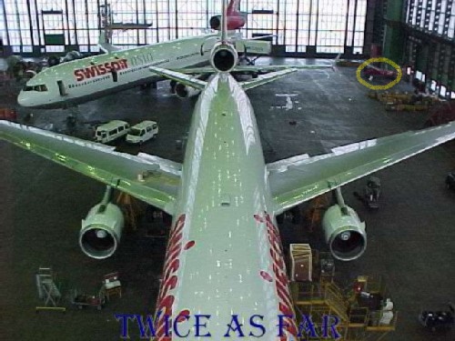
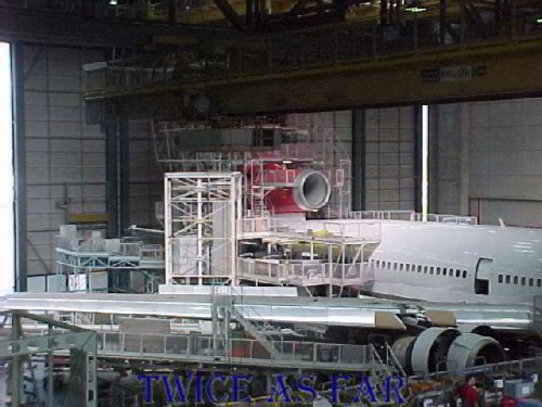
During the three trips to the Swissair hangar in Zurich, seven weeks were spent in the forward area of the MD-11 aircraft and with the associated equipment. This MD-11 in the foreground is undergoing an interior refit after having received a new exterior paint job. There is a second MD-11 in the background. While at first, they may look small in these two photos, there are two full sized nine-passenger vans parked on the hangar floor between the two planes. Also, against the right wall just inside the large hangar doors is a small red airplane that I have circled in yellow. Its photo is below.
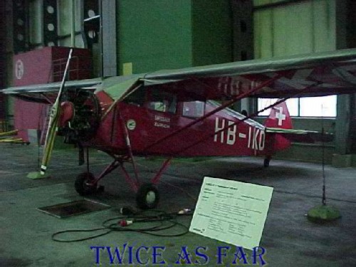
This single engine airplane was the company's first aircraft and is on display in the hangar. Note that the airplane is anchored down from the wings with cables to weights on the floor. The hangar doors are so large, and the winds can be so strong that the plane would otherwise be blown about without the tie downs.
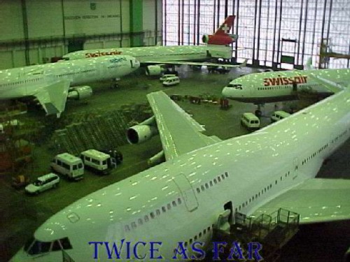
At the beginning of the second trip, this Swissair 747 was in the hangar along with these three other MD-11 aircraft. It can be seen that one of the engines is missing from the 747 in the foreground. The other three aircraft are MD-11 aircraft. The left-most aircraft belongs to Sabena Airlines while the other two are Swissair aircraft. Keep in mind that the tails are nearly sixty feet or just under twenty meters from the floor to the top of the vertical fin, and the vehicles are full-sized vans.
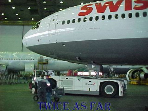
On the hangar floor, the aircraft presents itself as massive with the fuselage being about twenty feet in diameter. The photo shows John Garstang speaking with one of the SR Technics staff. The vehicle behind John is the tow motor that is used to move the aircraft. It picks up the nose wheel and carries the front of the plane. This particular aircraft is HB-IWE, the aircraft that was used for the Long Beach Air Flow Tests and it was built side by side with HB-IWF, the plane that crashed. The letter 'E' is painted on the nosewheel doors.
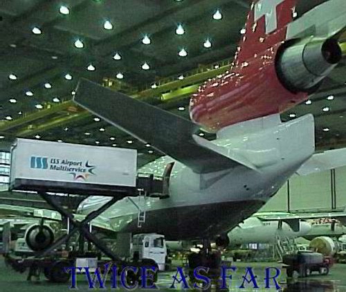
This photo provides a view of the rear of the aircraft showing how massive the tail assembly is with its number two engine. The top of the assembly is nearly sixty feet high, or as tall as a six storey building.
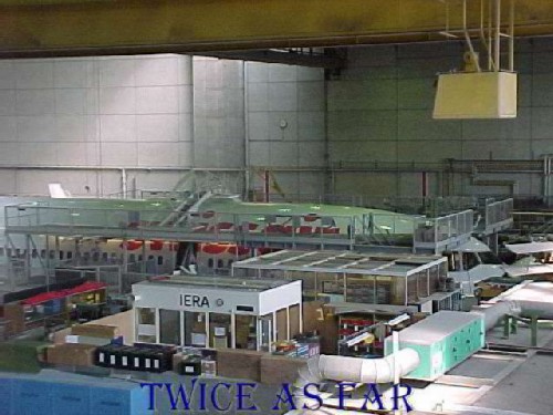
Another area of the Zurich hangar complex is the paint hangar.
Here the complete plane exterior is cleaned, the old paint stripped, and fresh paint applied.
Needless to say, it is a major operation that requires the positioning of extensive amounts of walkways and platforms.
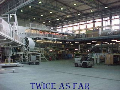
The number two engine is at the photo's centre.
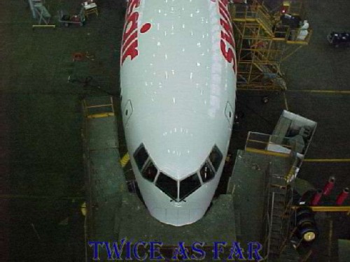
The forward section of the aircraft.
| ------------ SITE MAP ------------ |
* * * * * * * * * * * *
THE MD-11 INTERIOR
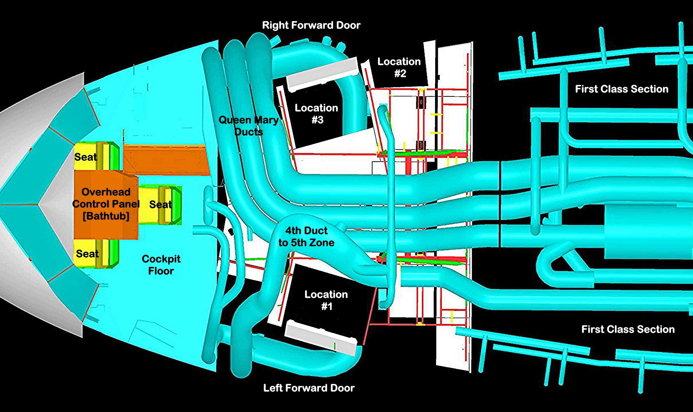
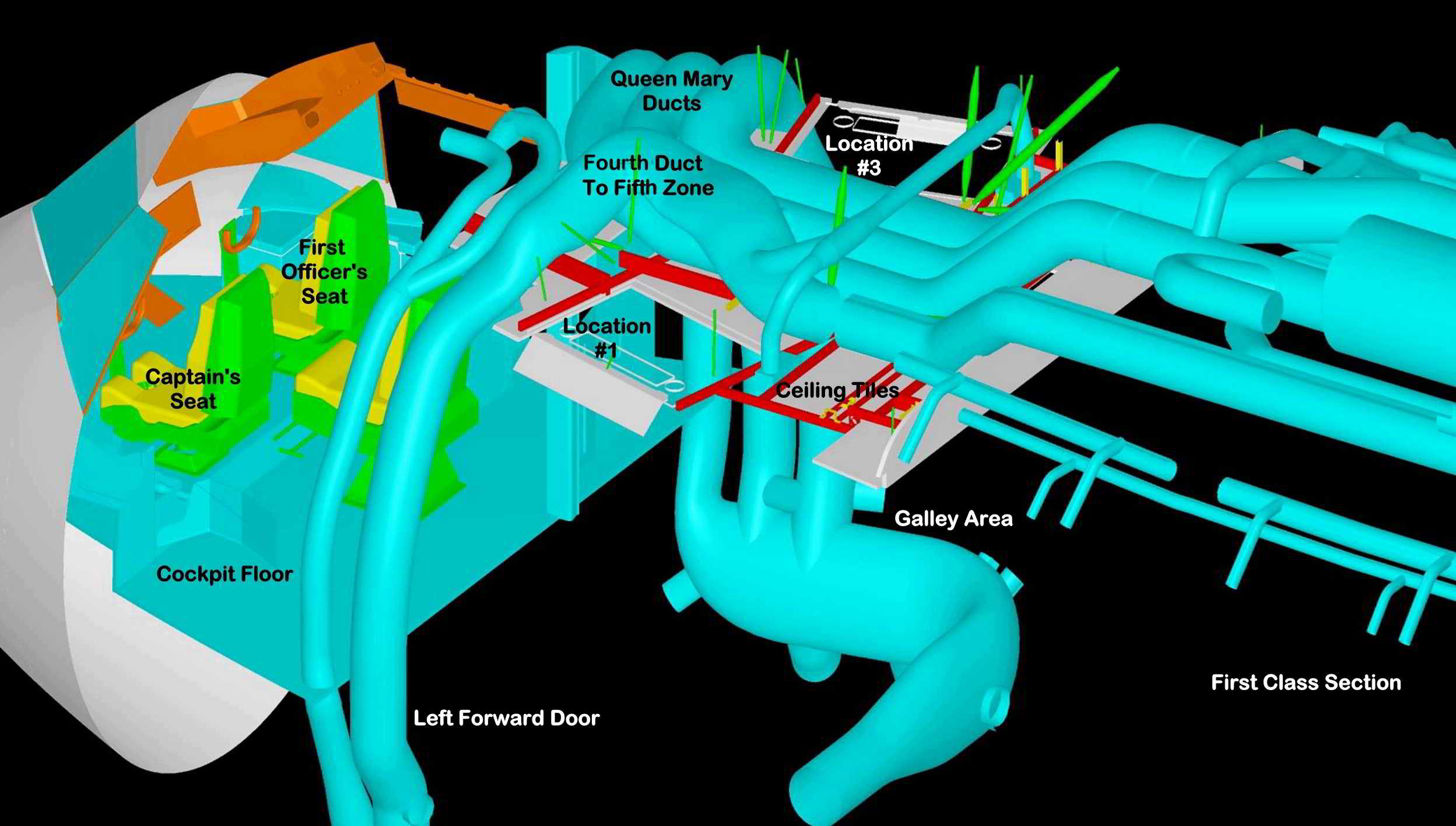
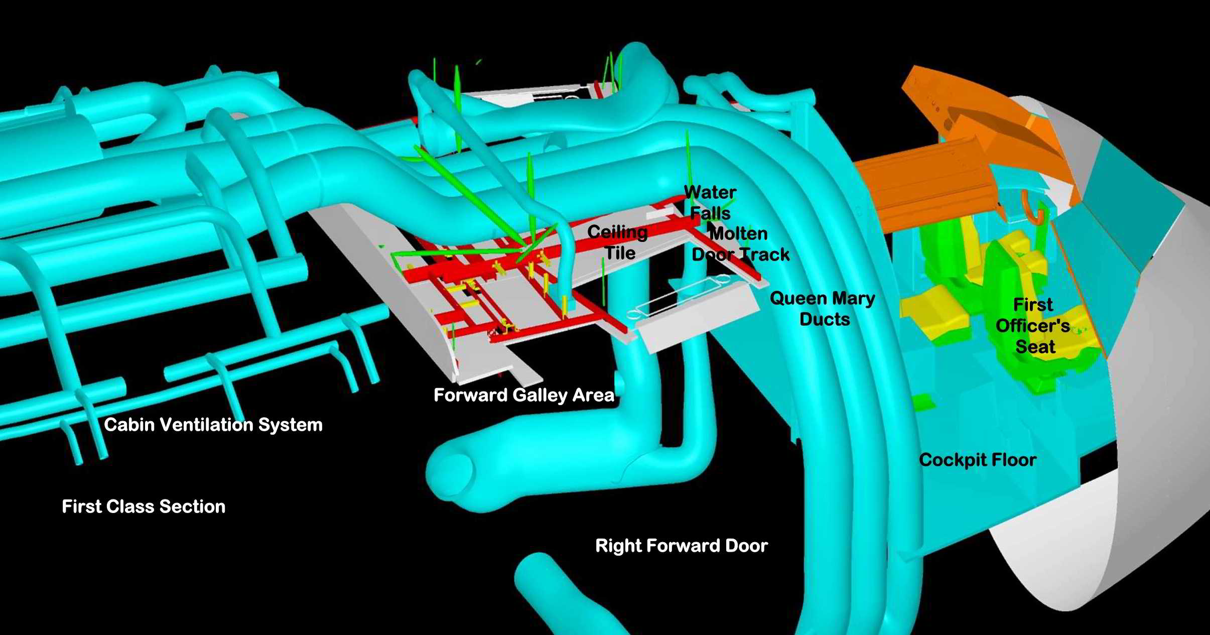
The following are three CAD images of the forward overhead area of the MD-11 aircraft.
They show the main duct arrangements in relation to key areas of the aircraft
In the first two images, the cockpit with its three crew seats is on the left.
To the right and above the seats are bluish coloured air handling ducts.
The three ducts together as a set are called the Queen Mary Ducts
with the 4th duct to the 5th zone on the left of the aircraft.
The white panels underneath those ducts are the ceiling tiles overhead the forward galley area.
Several location indicators have been added to the images
to allow the proper orientation of the photos that follow.
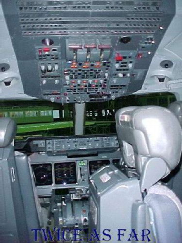
This picture shows the forward portion of the MD-11 cockpit with the display consuls functioning. The seat in the lower right corner of the photo is the third or observer's seat and is positioned sideways for this photo. During the three trips, several thousand photos were taken of the cockpit area. In this photo, everything is in its normal and functioning condition. The requirement was to show what was behind the panels and wall coverings. The panel in the upper centre of the photo is the face of what was called the bathtub. The panel contains some of the overhead switches and controls to run the aircraft.
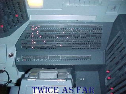
This photo shows the right side of the cockpit with one of the circuit breaker panels called the avionics circuit breaker panel at the photo's center. To the right on the rear wall of the cockpit is the main circuit breaker panel. The panel on the left is part of the bathtub with its overhead switches and controls within easy reach of the two pilots. The third seat is in the lower portion of the photo.
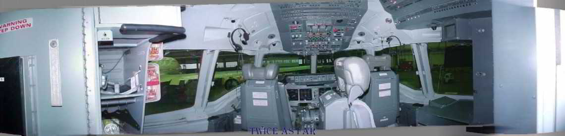
This photograph is a 180-degree panorama view of the cockpit of a Swissair MD-11 aircraft taken from just inside the entry door.
The Captain's seat is on the left with the First Officer's on the right.
The third seat, shown sideways in the immediate foreground, is at the rear of the
cabin and serves as a seat for a third pilot on long haul flights. One of the fuse panels cannot be seen in this photo
series as it is on the rear cabin wall. The avionics circuit breaker panel is at the upper right and only partially seen.
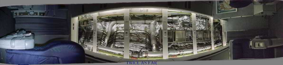
This panorama photo shows the equipment that is above the right aisle ceiling panels in the first class section of the aircraft.
Forward is to the photo's left. There are cable runs and air ducts as well as
electronic equipment towards the rear of the space.
The shiny silver material is Metalized Mylar that encases the fibreglass blankets of insulation.
Covering the air ducts is a duller looking grey material called Metalized Tedlar.
Metalized Mylar was found to be flammable at normal fire temperatures.
Metalized Tedlar did not burn in a fire of normal temperatures.
In reality, there is not much flammable material by weight in this space.
The fire appeared to have reached about half way into this area
to a point directly above the camera.
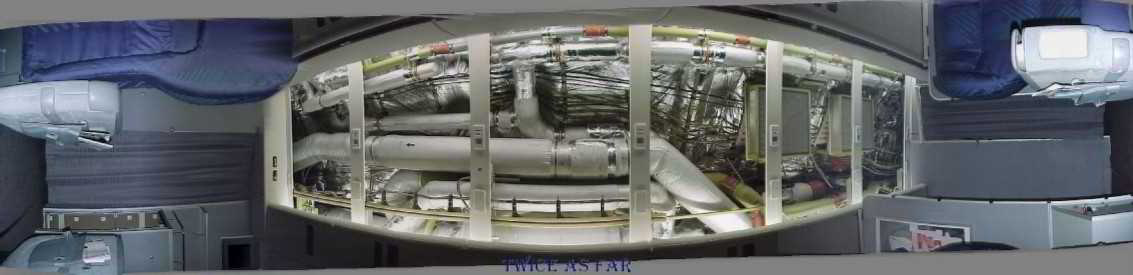
This panorama photo shows the overhead area on the left side of the first class cabin and again forward is to the picture's left.
There are a few more air handling ducts, most of which are similarly covered in Metalized Tedlar.
Some of the green painted ducts are not insulated.
The red bands around them are plastomeric joints that were found to be flammable.
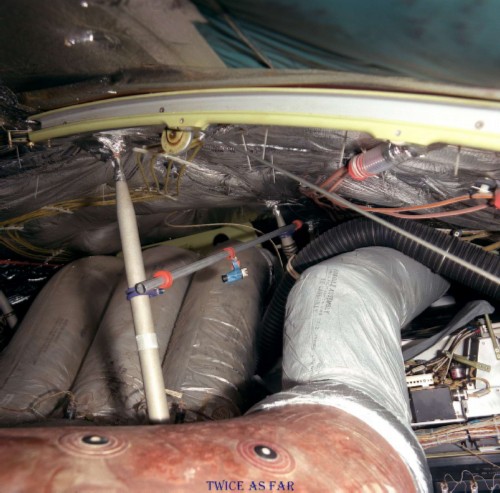
Photo from Location #1 in the CAD images.
This view, taken from above the left forward door area, shows some of the overhead space looking aft and above the galley area. Viewed from high up in the attic area, in the foreground and running up along the right side of the photo is the duct that is unique to the Swissair aircraft and those of only a few other companies. It is the fourth duct to the fifth zone and is made of a foam-like solid material. The remainder of this duct is wrapped in Metalized Tedlar. The other three main ducts to its left appear in this photo to be wrapped in Metalized Tedlar. This photo was taken on HB-IWE during the Long Beach airflow test, so a tiny blue and black camera on a support rod can be seen at the picture's centre.
During the inspections, only on two aircraft were the three main ducts wrapped in Metalized Mylar. Another black unwrapped duct goes laterally across the right centre of the photo. Across the top portion of the photo is a metal track on which the left forward door travels as it is pulled up and down by the stainless steel cable visible in the photo. Then there are other metal ceiling support pieces. At the immediate top right of the photo is a blue-green material that forms part of the insulation covering. It is present at these two lift doors to protect the insulation from the door movement, and it was later found to be non-flammable at normal fire temperatures. On HB-IWF, Metalized Mylar would have been the covering on the insulation blankets that were fixed to the ceiling skin. The Mylar covering on the ducts visible in the photo was most likely all Metalized Tedlar which was found to be non-flammable at normal fire temperatures. A fire with above normal temperatures caused by an accelerant would burn the Metalized Tedlar.
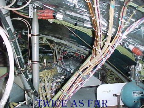
Photo from Location #2 in the CAD images.
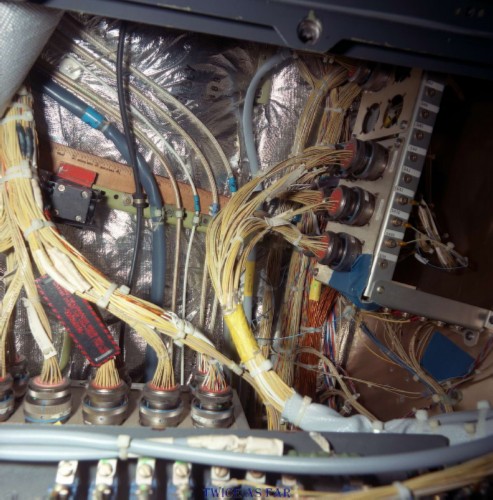
This image shows the overhead space above the right forward door, the other of the two forward doors that raise and lowers. This photo is taken looking forward. The door is in its closed position, so it is not visible in the photo. In the lower right corner of the photo is part of the door's compressed air system with a white partition and an empty area beyond. The ceiling tile at this space is one of the two thinner sliding tiles that are found only at the two lift doors. It is one of the two locations where the extremely burnt ceiling tile from Vaud could have come from, the other being the identical position on the left side of the aircraft. In the immediate foreground can be seen runs of wires all of which are bundled together by nylon ties. Just left of distant centre, the wire runs that have come from the circuit breaker panels in the cockpit at that point drop down from the ceiling and traverse towards the rear. This area is called 'the waterfalls.' Running from the lower right area of the photo just beyond the area of dark green ceiling material and curving up towards the upper left centre can be seen a strip of grey metal. This metal is part of the door track that on HB-IWF had received so much heat that it had bent on impact without breaking. Also, it had on it the 'broom-straw' molten metal. The dark blue/green protective material seen in the area of the photo just above this door track was found not to be flammable at normal fire temperatures. Again in this picture, except for the Metalized Mylar visible in the upper right corner that covers the aircraft frame and skin, there isn't much material that was found to be flammable during the burn tests.
This area could have been quickly and easily accessed during the stopover in New York.
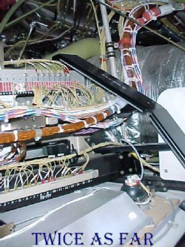
Photo from Location #3 in the CAD images.
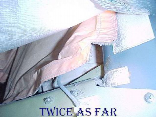
During the investigation, the area of wiring known as the 'waterfalls' was often the centre of attention. This photo shows why it was given this name. The cables or wires come out of conduits that pass overhead the main Queen Mary ducts after leaving the various fuse panels in the cockpit. When they emerge from the conduits, they drop down in a bundle to travel below the working space of the right forward 2.1 door as it raises and lowers. When the door is in its raised position, there would be insufficient room for them to pass between the door and the aircraft skin. They then continue to the rear of the plane. This photo shows a black door ramp or shield under which they travel. The angled shield ensures that the door and its attached pieces do not make contact with any of the wires. Above the shield and across the upper right corner of the photo can be seen the stainless steel cable that the door opening mechanism winds in a back and forth motion to allow the door to open and close. The shiny aluminium coloured object in the photo's right mid to upper background is part of the Queen Mary duct system wrapped in Metalized Tedlar.
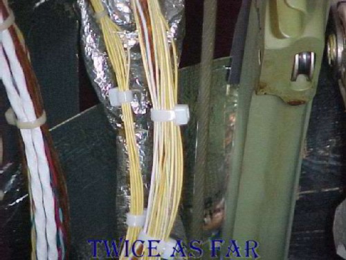
Photo from Location #3 in the CAD images.
This image
shows that same door cable at the photo's centre with the green metal object on the
right that is
the door track. On the left of centre are the wire bundles that are part of the
waterfalls area. The cable moves as the door drum rotates, so it
saws back and forth with only an inch of clearance. The cable is coated
with a heavy gauge plastic material
to prevent abrasion if it were ever to made contact with the wires. During the inspections of the many aircraft, not one showed any signs of
contact or abrasion of the wires. What's more, there is no door action
during flight, so any abrasion and subsequent wire damage resulting in a short
circuiting event would occur while at the terminal gate and it would be
immediately noticeable.
This
door track had suffered the extensive heat that had softened the alloy to allow
the rail to bend into a loop on impact.
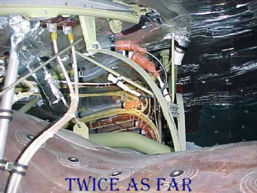
Photo from Location #1 in the CAD images.
This image was taken from above the left forward or 1.1 door and looks across the plane to the opposite right-hand side. Just below photo centre is located the waterfalls. To the middle right side of the photo can be seen the greenish-blue protective material above the 2.1 door. Across the bottom of the photo can be seen the fibreglass fourth duct to the fifth zone. Later tests showed that this duct did not burn at normal fire temperatures although the varnish like finish may burn for a short period if sufficiently heated. At the extreme top left of the photo is the door track for the 1.1 or left forward door that is fastened to the aircraft frame. Thus it is within inches of the plane's skin. It can be seen that there is not that much flammable material at this location other than the skin insulation with its four Mylar layers. Also there are the few ounces of wire insulation, none of which was found to contain magnesium, iron, or aluminium. It base component was found to be clay.
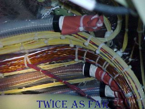
Photo from Location #1 in the CAD images.
From the position overhead the 1.1 door, this is a closer view of the waterfalls area and some of the maze of wires that flows to the rear of the plane. What is interesting is that it took nearly two years for Boeing to go through all of their aircraft design sheets to determine the routing of any one particular wire. To pick out one specific wire for a particular piece of equipment was impossible at the time. Remember that none of the diagrams for any part of the aircraft had been drawn by computer. Instead, it was the old system of a drafting table with paper drawings. Boeing converted many of the drawings to CAD, but it all took time considering the thousands of parts involved and the limited manpower for such an effort. Note that this is only one group of many dozens of wire bundle groups that travel back from the flight deck and forward E&E Bay.
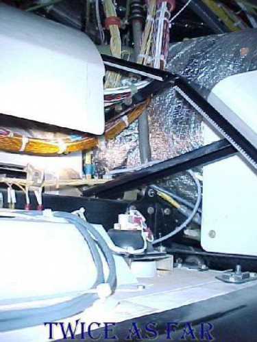
Photo from Location #3 in the CAD images.
This image again shows the waterfalls from the 2.1 door, but on a different aircraft. What is different is that there is a shield in place over the wires to the left of the black door ramp. The surface at the bottom of the photo is the top of the ceiling tiles for the galley area. This shield is of significance.
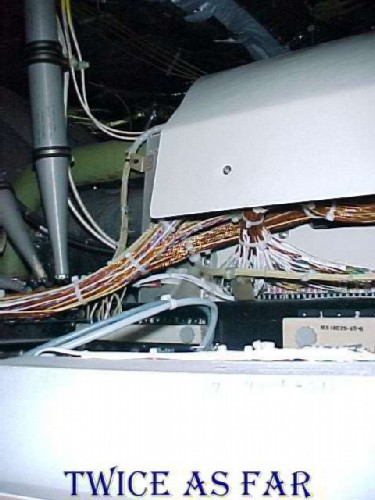
Photo from Location #3 in the CAD images.
This picture is the aft end of the shield and the continuation of the wire trail past the right forward door towards the rear of the plane. What is significant about these two photos is that it shows a piece of equipment that Boeing had requested to be removed from the aircraft some time before the date of the crash. However, this Swissair MD-11 and several others in its fleet retained this shield. This particular plane had not been through a recent 'D' check during which it would have been removed. It was noted to be in place on at least two other aircraft, including HB-IWE which was Vaud's sister ship. Both had been manufactured and delivered at the same time, and both had identical equipment configurations. The shield itself was not detrimental to the operation of the equipment, but it was merely weight which translated into fuel costs. It was redundant equipment once the black metal door ramp visible in the previous photo had been installed. However, its effect on a fire might have been significant in that it would have protected the wires for several minutes from an overhead fire that might have started in this location. It was a suitable surface on which to place an incendiary device. Of course, no evidence of this shield was identified in the debris and if present on the aircraft it likely would have been entirely consumed by the intense fire in this area. Indications were that it was not readily flammable without an accelerant and high temperatures.
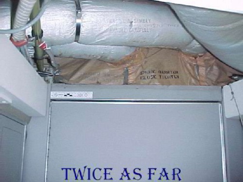
This photo shows the area above the ceiling hatch that is in the galley area just outside the cockpit doorway. The bottom of the view shows the door to the cockpit from the galley. The upper area of the photo shows two ducts wrapped in Metalized Tedlar (non-flammable) as they pass through an area that is closed off by what is called the 'smoke curtain.' It is a piece of non-flammable material designed to keep air and any smoke or fumes from going into the cockpit from the first class galley area, and it is supposed to be sealed tightly with the generic named Hook and Loop, or what is commonly called Velcro. At the left of photo centre is a six-inch scale ruler that has been placed in position. The hook and loop material is at the bottom of the brown coloured curtain to fasten and seal it to the grey structure as well as below each of the two duct openings. At the very best of times hook and loop tape is not air tight.
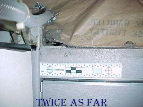
This photo is a close-up of the same area showing the bottom left corner and the fact that the curtain is not sealed securely. In fact, of all the aircraft inspected, only one or two had what might be called a completely closed curtain. This curtain has not been closed properly for a long time as is apparent by the dust. Also, the accumulation of dust indicates that the airflow is forward into the cockpit area due to the air circulation system at that point. There was no way to say what the condition was of the curtain in Vaud at the time of the crash. However, the seal could never be air tight. As for dust, this is what Brian London referred to in his New York report as the dust and dust balls that contributed sufficient material to the fuel load to cause the extensive fire damage that was seen in the wreckage debris.
This photo shows another area of the smoke curtain that became evident once the galley was removed during the refit. The curtain is obviously not sealed and by the amount of dust accumulation it had been in this condition for quite some time. From what I observed, the smoke curtain could never have curtailed the movement of smoke from the above galley area to the cockpit. So the smoke first smelled in the cockpit could easily have come from overhead the galley area despite what the TSB may try to imply in their report. I saw just as many smoke curtains as did the TSB members.
This photo shows some of the cables in the aircraft and is typical of the numerous wire runs. Much of the wire in this photo is Kapton insulated, but it can be seen that wires are in neat bundles with nylon ties to hold them all firmly together. Where necessary they are then encased in protective materials. While it certainly is possible for a wire to be abraded by one means or another, the technicians servicing the aircraft are continuously on the lookout for 'swarf' which is metal debris from the filing or drilling of metal. These pieces can embed between the wires and over time chaff through the insulation to cause a short circuit. However, since much of the aircraft is an aluminium alloy with specific elements, it stands to reason that any swarf between two wires that might cause a short circuit would result in a melt that engulfs the piece of swarf. It would then cause that area of the bead to have a very high percentage of aluminium and its other alloyed metals. Since every inch of retrieved wire was examined and every short circuit was AES (Auger Electron Spectroscopy) probed, such a bead would have been identified. However, no such bead was found. The same would occur for any short against the aluminium alloy frame pieces. The TSB (Transportation Safety Board) electrical examiner gave the likely cause as a wire short circuit and indicated the possible cable. During the Seattle wire testing, one of the problems in making test wires was the abundance of re-solidified aluminium that was left behind when an aluminium probe was used to make contact with the copper wire. The aluminium probe was changed to one of copper so that the problem would not interfere with the AES testing.
So then one might suggest that it was wire against wire after chaffing of the insulation, but there was no evidence of that occurrence in any of the other aircraft examined. To point to that as the cause in this one aircraft is total speculation without any proof.
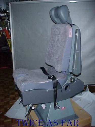
This arrangeent is typical of one of the seat setups for the object modelling process for the MD-11 Tour program that John and Louis created. Using Reality Studio software, thirty-six photos were taken of an object such as this cockpit seat with its wool seat covers in place, each photo showing a ten-degree turn until the full 360-degree circle was completed. One series was made horizontally, another looking down at about 45 degrees, and the third looking up at 45 degrees. The photos were then edited by removing the background, and then they were 'stitched' together in the software. Once done, anyone could examine any piece of the object as the software allowed one to zoom in on any part photographed. The final program created to view these images included wire beads less than one inch long by an eighth of an inch in diameter up to an actual MD-11 aircraft. All were object modelled.
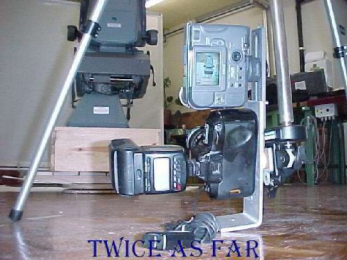
The photographic technique required the adaptation of equipment to suit the demands. The 35 mm Nikon F60 film camera was the mainstay camera for the job, but there was a need for instant photos. So the Sony Mavica was also used. Here they are mounted together on a bracket so that the two cameras can be used with only one turn of the exhibit. The Mavica used 3.5-inch floppy disks to hold about twenty image files. Therefore each rotation of the exhibit required two disks. Backup disks were immediately made, so that meant four disks per rotation. That is why more than five hundred disks were required for each trip along with several hundred rolls of film. The tripod was adapted in that several aluminium bars were made that replaced the central main shaft of the tripod. Each was about three feet long and one screwed into another to allow the camera to be set at floor level or more than ten feet into the air. Because they had to be transportable, they had to break down so they could fit inside the equipment boxes.
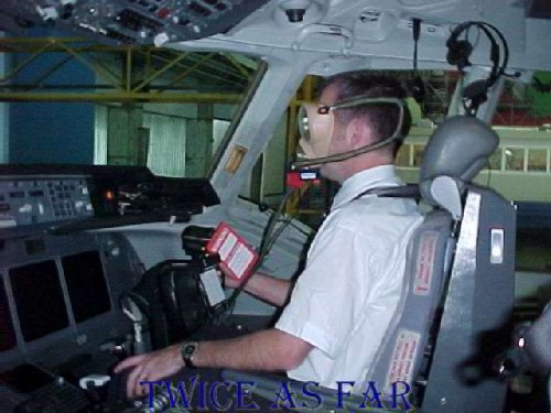
During the second Zurich trip arrangements were made to have one of the Swissair pilots demonstrate his manoeuvrability while wearing the full face mask on the flight deck. Here he is seated in the first officer's seat, or the right-hand seat. The control throttles for the engines are below his left hand. This facemask is the standard mask for the Swissair aircraft and the controls for it are on the chin.
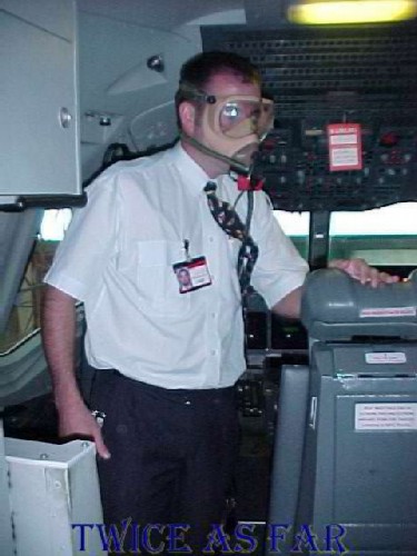
For this test, the pilot has moved to the captain's or the left seat and has come out of the seat to move to the back of the flight deck. The connecting oxygen line is long enough to allow him to move about and reach the back wall of the cabin. However, it is Swissair policy for the pilots to remove the face mask and don a PBE, or personal breathing equipment, for movement about the flight deck. It is a self-contained unit consisting of a complete hood that seals at the neck and provides oxygen for about fifteen seconds. After that, the perosn re-breathes the air within the hood which is good for about fifteen minutes depending on his or her rate of exertion and breathing. John Garstang had reservations about this policy when the cockpit is full of smoke.
* * * * * * * * * * * *
| ------------ NEXT PAGE ------------ |
| -------------- SITE MAP -------------- |
| ------------ Home Page ------------ |
![]()
![]()
![]()
![]()