
_svg.png)
TWICE AS FAR
SWISSAIR 111
CRASH INVESTIGATION
![]()
![]()
![]()
- THE INVESTIGATION -
THE DEBRIS RECONSTRUCTION
COCKPIT VOICE RECORDER
SEQUENCE OF EVENTS
|
SEQUENCE OF EVENTS RECORDED ON CVR |
||
|
GMT |
DURATION TIME |
EVENT |
|
00:18:15 |
|
Wheels rolling at JFK |
|
01:10:45 |
53
minutes into flight
|
First indication of
smell of smoke by flight crew. |
|
01:12:10 |
1:25 min (85 sec |
Cockpit door opened, flight attendant entered.
She advised no smoke in rear area. |
|
01:12:24 |
|
Visible smoke in
cockpit. |
|
01:14:37 |
|
Cockpit door closed. |
|
01:15:14 |
|
Smoke definitely
visible. |
|
01:25:40 |
14:55 min |
CVR stops. |
01:31:18 - 20:33 min - Seizmic event recorded as the moment of impact with the ocean.
5:38 min without CVR
| ------------ SITE MAP ------------ |
THE FORWARD GALLEYS
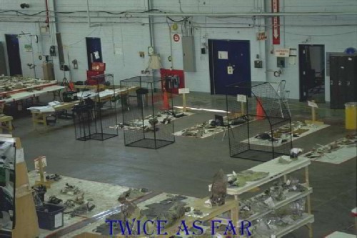
The fire seemed to have been confined to the forward section of the aircraft. However there was a need to determine if it had extended below the aircraft's ceiling. The best way to do this was to reconstruct the three forward galley units as best as possible, given the fact that they had been broken into thousands of small pieces. Three metal frames were built to match their size and shape, and this photo shows them located on the hangar floor with some of the debris pieces behind them yet to be put in place.
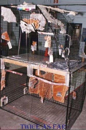
Due to the vast amount of destruction,
it was an impossible
task to reconstruct the forward galley units
totally.
The
best guess placement positioned many pieces.
However with the photos
of the new exemplar units available,
a sufficient number of pieces could be placed
so an
accurate story could
be told.
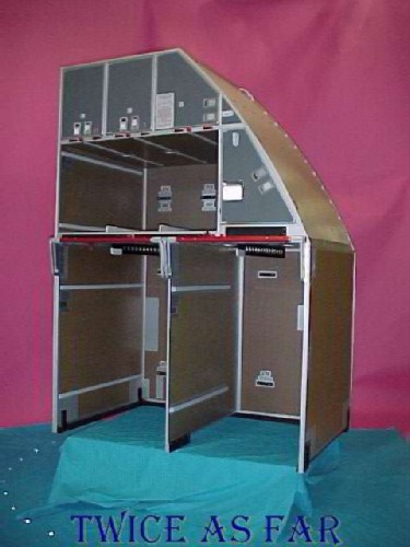
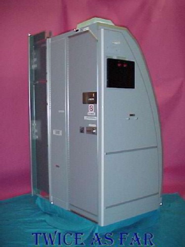
This photo shows a new exemplar unit of the right forward lavatory for the first class area.
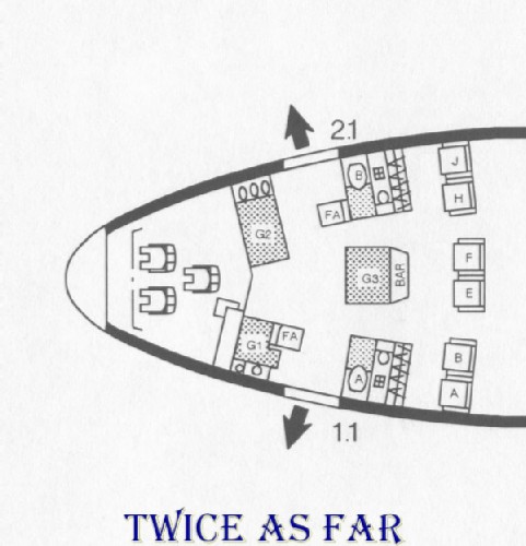
This diagram provides a layout of the forward section of the aircraft's cabin floor. It is the area that was rebuilt in the reconstruction jig that was so often presented in the media. The right forward door 2.1 can be seen along with G1, G2, and G3 as the three forward galleys. A and B are lavatory A and lavatory B. The passenger seats start with A on the left side or the Captain's side of the aircraft. FA at both the G1 galley and lavatory B are fold-up flight attendant seats, and the left forward door is marked as 1.1.
The site of the major burn was overhead of the area between the G2 galley and Lav B. The carpet area with the major melt damage was in the aisle between Lav B and the G3 galley. The duct called the fourth duct to the fifth zone is overhead of the 1.1 door area between the G1 galley and Lav A. The door that was open for servicing crews at JFK airport was the 2.1 door or the right forward door. The hatch that allowed easy access to the overhead area is in the aisle ceiling between the Lav B and the G3 galley. It is overhead the carpet with the most damage.
| ------------ SITE MAP ------------ |
* * * * * * * * * * * *
WIRE IDENTIFICATION
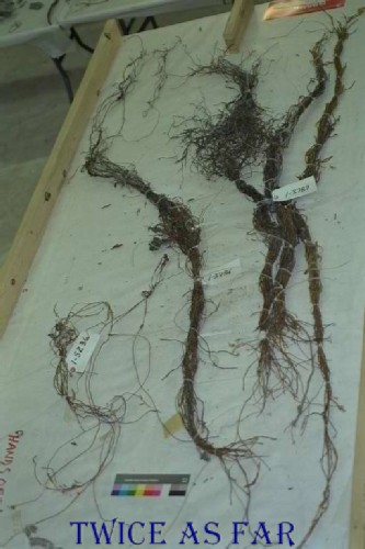
These photos show some of the wire bundles after recovery and sorting. The cables in the photos are in what would be their first relatively 'clean environment' since the crash. However, even here cross contamination of insulation materials and plastics from the aircraft is ongoing as the dust in the air of the hangar was continuous. Everything was constantly being moved about the hanger. Throughout, placement of wires such as these shown in the wire reconstruction jig was partly dependant on the material that had adhered to the outside of those previously burnt and heat scoured wires. Such placement would certainly be rejected by a Court of Law.
| ------------ SITE MAP ------------ |
* * * * * * * * * * * *
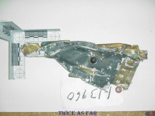
FRAME AND SKIN PLACEMENT
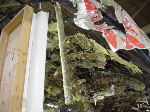
One of the problems with the various pieces of duct material was that they had been so badly damaged at the moment of impact, and then later on by the recovery. Many pieces came in totally crumpled, and to most, they would appear to be nothing but a clump of metal. However, the Air Force technicians were able to do a masterful job in reconstructing those crumpled pieces to reform many of the original ducts. Due to the complexity of the task, they could never be one hundred percent accurate. During the investigation, several ducts were found to have been incorrectly reconstructed. One of the reasons for this was because the TSB refused to undertake a proper method of physically matching the pieces. There was an attitude emanating from within the TSB's hangar management that filtered down to a few of the floor workers. Because they did not need to go to court with their material, close enough was good enough for much of their work. The thought process was that if any particular piece was later found to be incorrectly assembled, that piece could then be adjusted. That attitude was unacceptable for anyone used to conducting an investigation that would result in court proceedings, and it was frustrating for the Boeing and Swissair representatives who had to cross-check the work continuously.
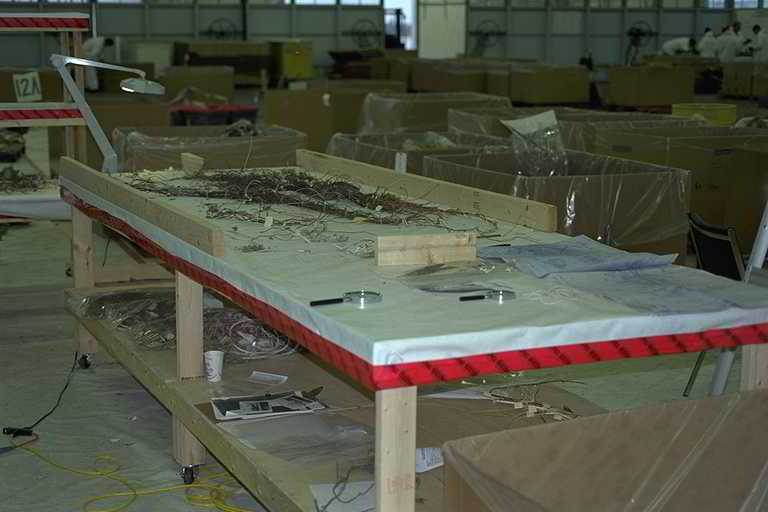
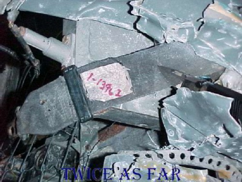
This photo was taken at the right rear corner of the reconstruction jig, and it shows one of the ducts that was reconstructed, but that has not been fully positioned. The viewer can also see some of the other pieces that have been positioned, many of which were properly physically matched with its adjacent pieces. Note the amount of green paint that can be seen. It indicates that the piece did not get hot enough for the paint to discolour or burn. The insulation blankets remained in place at those positions, so at least one layer of Metalized Mylar was not consumed in the fire.
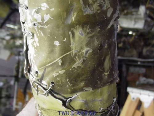
This photo shows a close-up of one of the joints in the duct shown above. Due to the jagged edges, it was a relatively simple match to make. Not all were this easy. Also, note the discolouration of the paint except for the area of clean, green paint. At that point, the duct was strapped with a collar. The discolouration is soot on the paint. This un-insulated duct was far enough to the rear to not be in the fire, but it shows that there was heavy soot in the atmosphere above the ceiling.
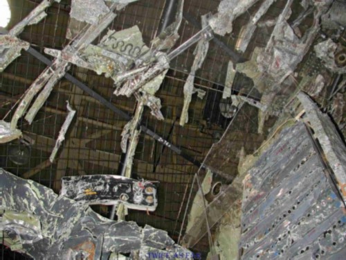
This photo was taken at the right rear corner of the cockpit. In the lower right corner is the main circuit breaker panel. The Avionics circuit breaker panel would normally be at the lower photo centre, but it has not yet been installed. Of interest is the amount of material that is attached to the reconstruction jig and the skin pieces in the immediate area, or lack thereof.
What is present shows signs of the paint having been burnt in some areas and
un-burnt in others. Even in the top right corner, or high up where the
heat would accumulate, there is green paint.
This location is the position given by the
TSB as the source of the ignition of the fire by a
short-circuited wire.
There is
little physical structure on which to base that speculation, for that is
all it is.
Note the piece of Plexiglas in the lower right area, a piece added to assist in the reconstruction of the main circuit breaker panel.

The top of the piece of Plexiglas from the previous photo can be seen in the lower portion of this photo. Above and beyond, looking towards the rear of the aircraft reconstruction jig can be seen more frame and skin pieces. Note the paint condition of each piece. Many have the paint burnt completely off in the lower portion of the piece to the point that the metal is discoloured. However, just a few inches higher, the paint is still green, although in some cases somewhat soot covered. Much of the skin is un-burnt. Each piece was examined and physically matched to the next, so they all belong exactly where they are positioned. The lack of paint damage was troublesome for me. During the Zurich trips, it was realized that it was a strong indicator of the amount of fire load that burnt. Remember from the trip photos that the insulation is made up of two layers of individual blankets. The blanket next to the aircraft skin is a small blanket that fits within the frame region to cover the skin and some of the frame material, but it leaves exposed the edge of the frame furthest from the skin or the innermost edge. Then a large insulation blanket covers that including this innermost edge of the frame.
If during the fire, the large innermost blanket burnt and that insulation factor was removed, the fire would scour and burn the innermost edge of the frame pieces. However, to keep the green colour on the remaining area of the frame, the small outer insulation blanket would have to remain intact and in place. So, while two layers of the Mylar on the large blanket would have burnt, at worst only one layer of the Mylar on the small next-to-the-skin blanket burnt. The insulation would have protected the layer that was against the skin of the aircraft. The significance of this is that only three-quarters of the Metalized Mylar that was present in this portion of the aircraft would have been consumed in the fire thus reducing the fire load by 25%.
This fact also accounts for there being so many holes in the skin area of the reconstruction jig. During the sorting of the pieces, it is possible that many of those skin pieces that were not obviously from the forward area or that showed no burning or soot staining were put in storage boxes and shipped to J hangar. Many of those stored pieces might have belonged in the forward section of the aircraft and were not picked because they were pristine in colour.
| ------------ SITE MAP ------------ |
* * * * * * * * * * * *
MOON WALK
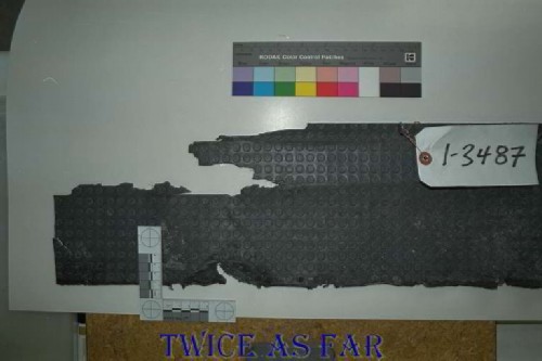
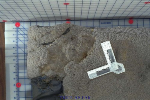
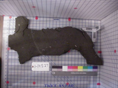
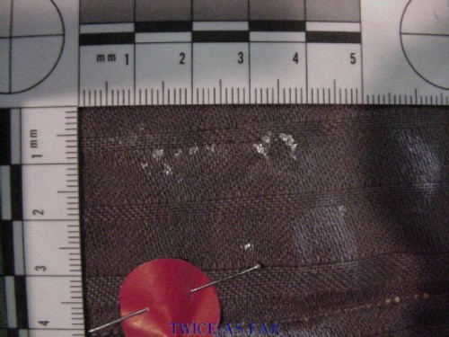
This material is 'moonwalk', the galley floor covering, so named because of the small raised circles. Note the area to the right of the scale ruler in the photo's lower portion.
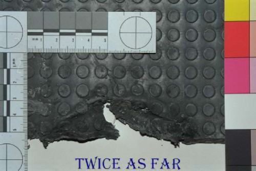
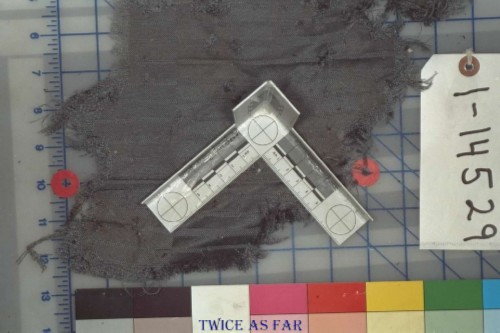
This photo shows the area from the previous image and it indicates that the material has suffered heat damage. The vinyl-like material has melt damage and embrittlement indicating that something very hot came into contact with it.
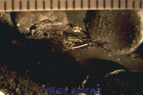
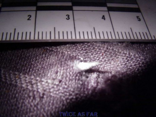
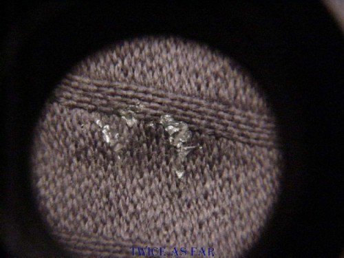
This view is a close-up of that melted area showing pieces of metal debris embedded in the material. At the moment of impact as the nose of the aircraft contacted the water, this area would all rush forward and into the water within milliseconds of the impact. There would not be sufficient time for anything to fall the eight or so feet to the floor within that time frame. Also, the TSB determined that the aircraft was possibly upside down when it hit the water. So whatever caused this heat damage to the flooring likely did so during the pre-crash fire. As for the tail engine passing through this area, remember that it had been shut down and was wind-milling, or the flow of air through the fan blades was causing it to turn. Thus it would have been cool and could not have done this damage. The other engines would have sheared off their mounts upon impact and fallen away from this area.
With the evidence of this vinyl carpet and the heat damage as shown in the photos above
along with other evidence including the AES suspicions,
there was ample reason to suspect something was amiss
and that it was not merely an accidental and 'normal' aircraft fire.
| ------------ SITE MAP ------------ |
* * * * * * * * * * * *
HIGH HEAT & LITTLE TO BURN
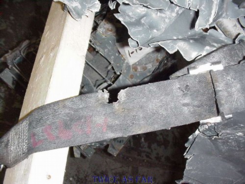
This series of photos shows the location of the forward door track that had suffered so much heat damage. Broom-straw metal effect was found on it in addition to it being bent to a full closed loop from its normal arc consistent with the curvature of the aircraft hull. When trying to straighten it, the piece broke. It must have been extremely hot at the moment of the crash to bend as it did without breaking. Keep in mind that the ceiling tile below it was possibly burning at 1700 degrees F for five minutes, or possibly 1100 degrees F for ten minutes.
The identity of the piece as the forward door rail for the right forward lift door, the 2.1 door in Swissair jargon or R1 in Boeing terms was proven by a physical match with a series of other pieces in the area.
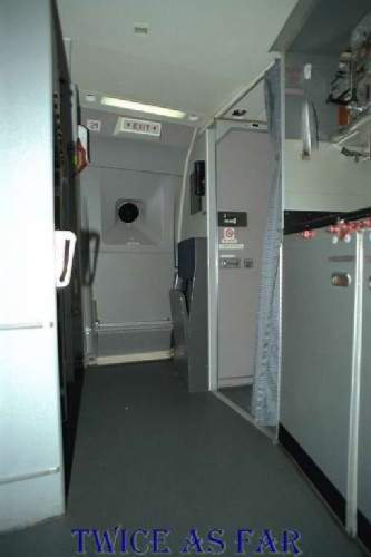
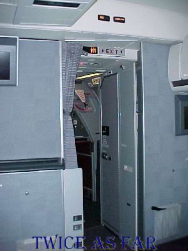
This photo, just left of centre, shows the 2.1 door in a closed position on an operational aircraft. The door has the exit sign above it, the blue and grey flight attendant's jump seat to its right attached to the lavatory wall, and the right forward galley on its left. Passengers do not normally enter or exit via this door, but it is open at the airport gate to allow access to the aircraft by service crews as occurred at JFK Airport on the afternoon and evening of the fatal last flight.
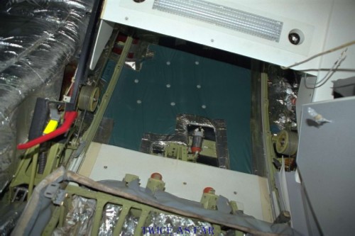
This photo was taken on an aircraft under refit with the walls and most of the ceiling removed. In the former photo, if one walks towards the door and looks straight up, this photo shows what can be seen directly overhead. With the door immediately in front of you, the top of the door without its covering is at the bottom of the photo. Above the door and to each side of it are two green rails and two green round pulley drums around which the lifting cables are wrapped. These pulleys are attached to electric motors that cause the door to raise and lower on the two rails. The forward rail is on the left, and this would be the piece of track rail that was so badly bent after the high heat. Between the two rails can be seen a green covering material used as protection for the insulation above it, or against the skin and frame of the aircraft. Tests indicated that this material failed to burn at normal fire temperatures. Very little if any of this material was retrieved as debris. The Queen Mary ducts are on the extreme left of the photo and the white material at the top of the photo is part of the ceiling tile material. As the door is raised, another piece of ceiling tile retracts over the piece seen at the top of the photo. This retracting piece at the doorway is thinner than any other pieces of the normally fixed ceiling tiles, and it is only found at these two door area positions. A piece of that material was shown to have burnt at 1100 deg. F. for ten minutes or more. The insulation wrap of the Queen Mary ducts on the left, during the Zurich 3 trip, was found to be the AN-34 Metalized Mylar that fails to maintain a flame front under normal fire conditions. However, sufficient heat due to an accelerant would cause all of these materials to burn.

The previous photo was taken at the right side of the aircraft when facing forward. As one steps backwards from the 2.1 door to the centre of the aircraft and looks up, still facing the 2.1 door, one can see the bend in the Queen Mary ducts as they turn and point to the rear of the aircraft at this photo's right side. The ducts at this location are covered in Metalized Tedlar, material that fails to maintain a flame front and burn under normal fire temperatures. One can see the outer wrap of AN-34 in the lower left corner, and the Metalized Tedlar continues under that wrap to surround each duct all the way to the floor.
| ------------ SITE MAP ------------ |
* * * * * * * * * * * *
BURNT CABIN CARPETS
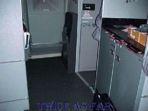
This photo is again in the forward galley area of the aircraft and looks towards the 2.1 or forward right door. One can see the flooring area consisting of the vinyl type of material called 'moonwalk,' a non-slip flooring. Each of the two aisles to the first class area has fabric carpet with a metal transition strip to hold down the nylon carpet end. The area is visible in this photo just below centre. Also visible, just above the two briefcases at the photo's bottom right corner, is a ruler and circular protractor to determine the angle of cut of the carpet.
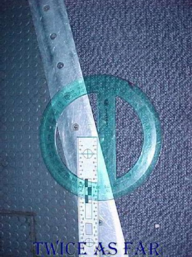
This photo shows the right angle ruler and the protractor in place to determine the angle of the cut. The moon walk is on the photo's left with the carpet on the right. In the lower left corner can be seen a repair to the moon walk material, visible in the photo above.
Note that this digital photo was taken at a non-perpendicular angle to the floor
to eliminate flashback, so the perspective is not accurate. The 35mm photo
of this view, not available, was taken perpendicular as a remote flash was used,
and the exact angle was recorded in notes. No other piece of carpet in the
aircraft had an angle such as this as the carpet on the left side at the same
station number had the opposite angle,
and elsewhere in the aircraft, other
carpet-ends were square cut.
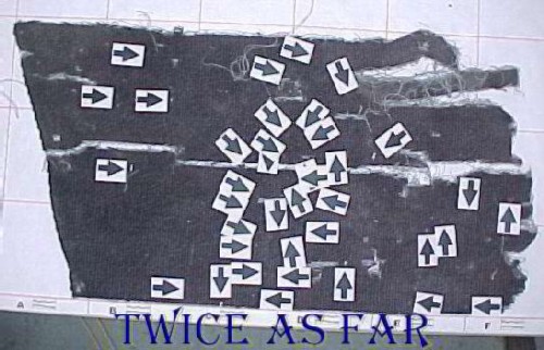
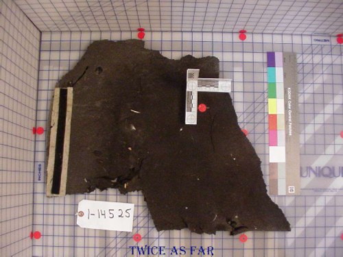
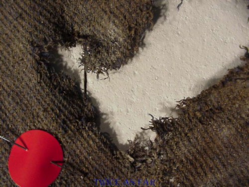
This image shows a piece of debris carpet. The angle of cut corresponds with that for the aisle carpet leading from first class to the 2.1 or right forward door area. The carpet has been photographed to show its upper surface. Located on that surface were numerous melt areas embedded into the carpet, and each has been marked with an arrow pointing to it, the exact tip of the arrow indicating the melt area, one per arrow. Disregard the tears in the material as they are mechanical damage due to impact and possibly the recovery process.
The significance of this is that something overhead was extremely hot; sufficiently hot so as to melt overhead materials. While the ceiling tiles would not allow the passage of molten aluminium through them, their support structures may have burnt or melted to cause their displacement. There are also speakers and lights in the overhead area that may have melted sufficiently to cause this damage. No matter what the source may have been, there was an extreme fire overhead on the ceiling tiles that resulted in this damage. As seen above, what was there to burn in a normal fire to cause this amount of damage? Metalized Mylar alone could not provide sufficient heat to cause the non-flammables to burn, yet it appears that those items did indeed burn!
This photo shows the forward partition of the first class section including the right aisle leading to the right forward 2.1 door. The carpet area shown in the previous photos is at the bottom of the photo, and one can see the various lights and speakers in the overhead area. This is perhaps the reason for the melts in the carpet below it. Note too that upon entering the first class area from the galley the overhead ceiling suddenly becomes higher thus allowing for the overhead baggage compartments.
| ------------ SITE MAP ------------ |
* * * * * * * * * * * *
AIRCRAFT FORWARD AREA LAYOUT

This photo is a look down view of the cabin and cockpit floor reconstruction area of the aircraft laid out on the hangar floor with carpet and galley reconstruction frames. The cockpit floor is higher than the galley floor by nine inches. The photo's right half shows the three forward galleys while a new exemplar cockpit carpet is laid out in the left half. The three galleys are in place while the two lavatories, A at the bottom and B at the top, are merely outlined as marks on the floor. Each of the three holes in the cockpit carpet is for one of the three seats fastened to the floor.
Some of the debris carpets have been identified and put in place, each being tagged with an exhibit number. The carpet area previously shown with the melts would have been located between the Lav B in the photo's upper right corner and the G3 Galley at the extreme right centre edge of this photo.
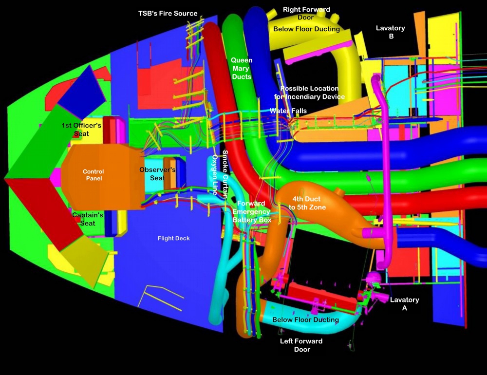
This image is a CAD reconstruction of the same forward area of the aircraft showing some of the interior overhead equipment.
The large blue area left of photo centre represents the cockpit floor with the three seats facing forward to the left of the photo.
They are clustered around the tan coloured object that is the overhead control panel, or what is called the bathtub.
In the upper centre of the photo, behind the blue cockpit flight deck, are the three air ducts coloured red, green and blue
that are the 'Queen Mary ducts.' They come up from below and go into the ceiling area by following the curve of the aircraft's hull.
They are located just ahead of the right forward 2.1 door, not shown in the photo.
The ducts flow to the aircraft's centreline in the overhead ceiling area
and then they turn towards the back of the aircraft as seen at the photo's centre and right half.
Along their length on all but two of the inspected aircraft they were wrapped in Metalized Tedlar.
At photo centre, just under the point where the ducts bend to turn aft
is the hatch with the forward emergency battery box with the large molten aluminium pendant.
Just ahead of that is the oxygen line with its fitting that may have leaked, but it points forward into the cockpit area.
At the photo's lower centre is another duct of a dark tan colour that flows up towards the photo's centre
where it rides over the red and green ducts.
This is the fibreglass - foam duct that is the fourth duct to the fifth zone.
At this point, the height between the ceiling tiles and the plane's central point is approximately three to four feet at the aircraft centre line.
Just above the photo's centre, running across the red, green, and blue QM ducts can be seen a wire run.
Where they fall over the blue duct is the area called the 'waterfalls.'
The fire source location pointed to by the TSB is just a few inches ahead of the red QM duct at the upper edge of the aircraft.
The location for a possible incendiary device was possibly in the area just aft of the QM ducts as they traverse towards the aircraft's centre
and above the blue duct as it turns towards the aft of the airplane.
This area is only a matter of four feet or so aft of the TSB's possible location.
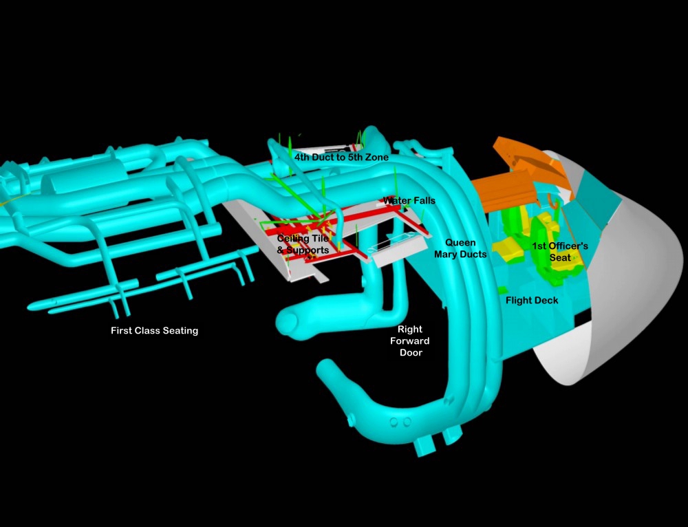
This CAD image shows a high angle side view of the aircraft equipment with the flight deck to the right and the seats in yellow and green.
To the left and behind the flight deck are the three Queen Mary Ducts visible as they follow up the inside of the aircraft's hull
and then in the overhead area at centre, they turn aft.
Where they turn aft, below them can be seen the off-white coloured ceiling tile material for the forward galley area.
The red bars are part of the ceiling support frame.
The openings in the ceiling correspond to hatches to allow for overhead maintenance and to the sliding right forward 2.1 door panel.
The recirculation fans are located at the photo's extreme left and beyond the view of this image.
The wire run is not shown in this image.
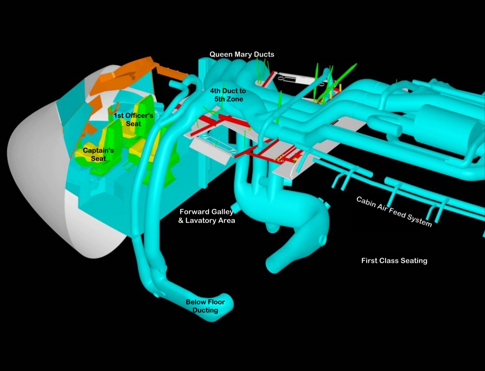
This CAD image shows the left side of the aircraft with the duct rising up on the inside of the aircraft's hull
to turn into the fourth duct for the fifth zone at the point where it turns aft, just above the photo's centre.
The left side ceiling structure is in place, and it is nearly a mirror image of the right side.
At the point where the ceiling tiles suddenly rise is the start of the first class cabin area, as noted in the actual cabin photo displayed above.
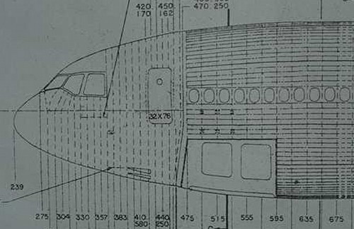
This image is a scale drawing of the aircraft nose area, left side view and just left of centre is the left forward door or the 1.1 door.
The door is 32 inches wide by 76 inches high, and the ceiling tiles are just a few inches above the door frame.
This side view shows that the top of the aircraft hull in the fire area rises as one goes aft.
The numbers across the bottom designate inches in the 'Y' coordinate for the plane.
The front edge of the nose is 239 inches behind point 0. As one goes towards the rear of the aircraft, the distance in inches increases.
Thus if a piece of equipment is located at a point 440 inches behind point 0, it is actually 201 inches from the front edge of the aircraft.
This measurement number from 0 for each piece of equipment location becomes what is called the station number for that particular item.
The reason for this is that when an aircraft is first drawn out on paper or now on the computer,
allowance is made for modifications or for stretching the hull by adding segments to accommodate various requirements.
Once everything is set for the final design and tests, there is no reason to adjust the measurements or station numbers.
In fact, the MD-11 aircraft is the design of the MD-10 aircraft with two segments added to the hull fore and aft of the wings.
So when looking at the design drawings of the aircraft, the MD-11 hull was in fact 'stretched' on paper.
Of course, everything behind those additions has to have a new adjusted station number, increased by the length of the additional segment ahead of it.
Note the station number 383 on the bottom of the sketch.
This point on the opposite side of the aircraft just behind and above the right window frame
was the location of the first electrical event that the TSB established
and by speculation determined that it was the cause of the fire.
| ------------ SITE MAP ------------ |
* * * * * * * * * * * *
COCKPIT SEAT RECONSTRUCTION & MELTS
COCKPIT SEAT RECONSTRUCTION & MELTS
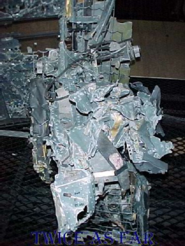
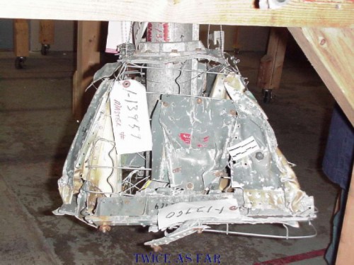
Don Enns was able to reconstruct the third or right observer's seat that was in the cockpit. Swissair uses the seat for their third pilot when on long distance flights. For this flight, the seat was unoccupied. Don put more than a thousand pieces together to make up the seat, and he located some interesting details. Here it is seen in position in the reconstruction jig in the hangar.
During the Zurich 1 trip, an exemplar seat was object modelled to assist in reconstruction. The background would be totally removed digitally for the MD-11 tour program that was created to view much of the wreckage and an actual aircraft.
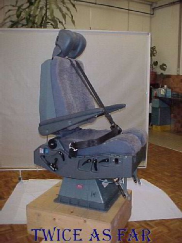
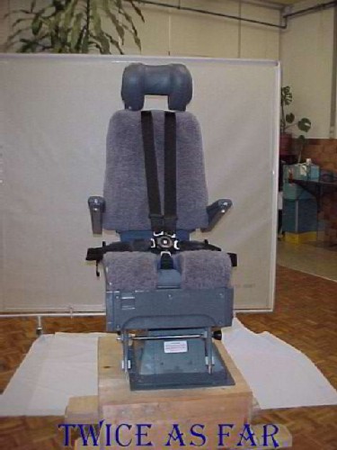
This photo is a side view, one of the many shots taken of the seat for the tour program. The chair's metal base on the wooden box is important in this photo. The face towards the camera shows a small red label, and just to the right of it on the same metal face is a black object that is a circuit breaker.
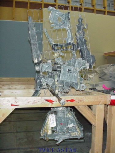
This photo shows the reconstructed seat with the base attached but positioned below the table's upper frame.
This image is a close-up of the chair's base. The remains of the red label and the small circuit breaker can be seen at photo centre and to the right of photo centre. The scale measure is just above and to the button's left.
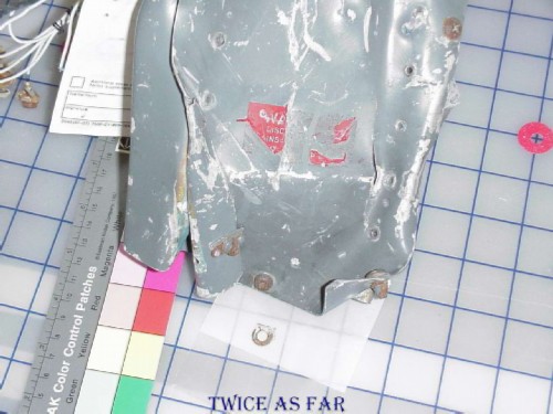
The photo shows the central piece with the remains of the red label. Of note, directly below the label at the bottom of the piece of metal is a threaded bolt. Below that, on the piece of paper, is the washer that was on that bolt, but it now has been removed, and the bolt replaced.
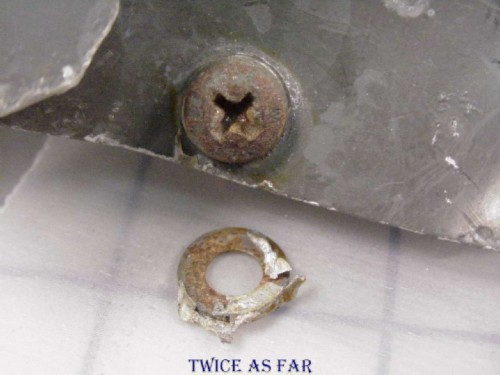
This view is a close-up of that washer, and on its surface is molten and solidified aluminium.
This photo shows the piece of the seat base with the circuit breaker.
A close-up of the circuit breaker mechanism shows more molten material, likely ceiling plastic. The TSB had both melts analysed, but restrictions imposed by Lathem and Fraser prevented me from learning what the results were. It is suspected that if it was plastic, it came from the overhead ceiling liner. If it was aluminium, which is likely for the washer in the previous photo, it could be from any overhead source once the ceiling liner melted. However, it is on the right side of the seat base, so the material had to have come from that side. The oxygen line is located above and behind the chair, at about the seat's centre.
| ------------ SITE MAP ------------ |
* * * * * * * * * * * *
MORE MELTS ON THE FLIGHT DECK SEATS
MORE MELTS ON THE FLIGHT DECK SEATS
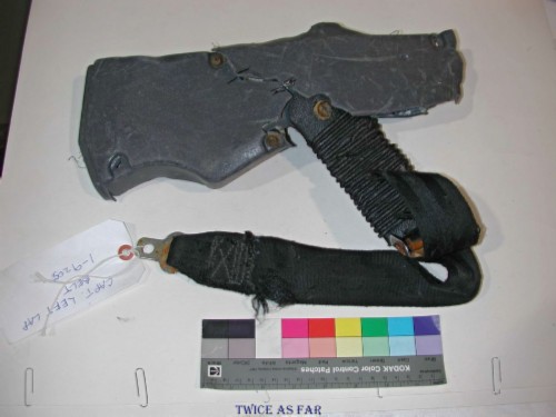
During the seat examination, areas of significance were found that helped tell the story of the last minutes of the flight. This photo shows part of the lap seatbelt for the captain's chair or the left cockpit seat. The belts are not a retractable type as is typical in automobiles. Instead, one belt segment is fixed to each side of the seat, and two over the shoulder harnesses meet at a buckle in the front centre. A sliding tightening buckle is utilised to allow the belt to be pulled tight once it is fastened into the buckle. This setup provides for a much more secure seatbelt system.
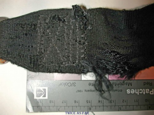
A closer view of the same lap belt shows the area of the strap near the metal hasp. The right half of the photo shows a damaged area of the belt. Close examination revealed it to have been damage likely due to mechanical means at the moment of the crash or post-crash recovery. It is an isolated area not consistent across the width of the whole belt. Of importance are the stitches and the area fixed together by those stitches. There appears to be no stretching whatsoever in the thread or the fabric on either side of the belt. Standard operating procedures under such circumstances are that if the pilot was in the seat, the belt would be fastened securely. It would appear from this seatbelt that the pilot was not in his seat, but instead was behind the seats likely trying to fight the fire as long as he could as it came through the cockpit ceiling. Up until the six minutes of lost time in the CVR (cockpit voice recorder), both pilots were in the cockpit. During the last six minutes, it was believed that the first officer was flying while the captain was trying to fight the fire that had eventually entered the cockpit ceiling area.
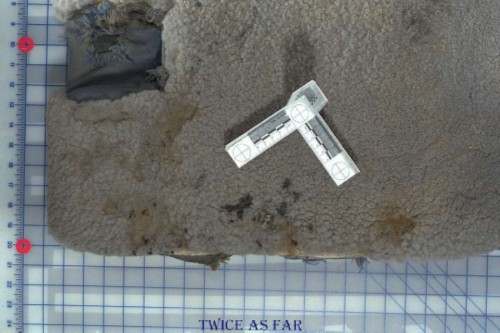
This photo shows the seat cushion of the right observer's seat, or the third chair in the cockpit, and in particular the area of the seat cushion under the left leg of a seated person. It is the seat that is aft of the other two and is for the third pilot if one is carried onboard. Note that a fourth seat is in the cockpit, but it is a folding jump seat in the left rear corner of the cockpit. This photo shows an area of the wool seat cover that indicates a melt area within the angle of the scale ruler. Something molten that then solidified is in the wool fibres. To the left of the ruler is an area of the seat cover that appears to have had the wool fibres torn away, a situation similar to that found on the carpet of the cockpit floor. This seat would have been unoccupied during the flight. Great effort was made to ensure the accuracy of the seat cover placement once most of the material was retrieved. Unfortunately, some small pieces were never recovered.
This shows the area of the same seat cover under the right leg of a person seated in the chair, and it shows a similar area of wool fibres having been torn away. An occurrence similar to this was seen on the cockpit floor carpet, and it was determined that molten plastics had landed on the surface, solidified, and then were torn away by the forces of the impact, thus shearing off the fibres.
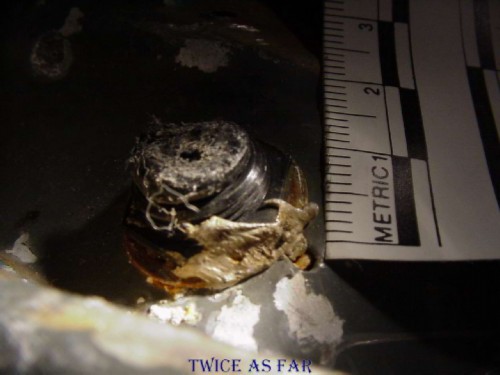
This shows the lap belt, left side, for the same rear cockpit seat called the right observers seat, and it shows an area of the belt that has been melted due to something hot dropping on it.
This photo shows the right side seat belt for the right observer's seat and to the left of centre of the photo is the stitching area of the belt. On the left portion of stitching in the photo can be seen two areas of what appear to have been molten material at some time, possibly aluminium alloy, that had then solidified on the belt. A knife is at the right side of the belt as the photo was taken with the digital camera just before the belt was to be cut. The cut piece was then sent for lab analysis. Again, due to Lathem's and Fraser's restrictions, I was never allowed to know what the evaluations of the lab analysis were.
| ------------ SITE MAP ------------ |
* * * * * * * * * * * *
MELTS ON OTHER SEATS
This photo shows one of the first class seat cushions that shows an area of possible melting. The angled ruler and red marker indicate the location of the possible molten area.

This image is the area in question. The foam was sent off for lab examination, but it was another example of an exhibit analysis that I was not to know the results. John Garstang and others felt that it could have been heat damage, and it gave every indication as such.
This object is the second of the recovered first class seat foams that showed indications of heat damage. A third foam that I do not have the photos for was found and it appeared to have been perforated in several areas by heated objects.
| ------------ SITE MAP ------------ |
* * * * * * * * * * * *
MELTS IN THE CURTAINS
This material is a piece of curtain from the debris of the aircraft. The centimetre scale is positioned so that at about the 1 and 1 cm position is a small light grey point or speck on the darker grey of the material.
This photo is a close-up of that light grey point with the scale having been moved. It is a solidified drop of aluminium alloy that has penetrated the curtain fabric. The surface of the aluminium was rough enough to hold it in position and removing it caused fibres of the curtain material to be pulled away.
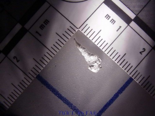
This photo shows the horn-shaped solidified drop of aluminium alloy. At what time it arrived in the curtain could not be determined, nor could the curtain's original location in the plane be confirmed.
Another piece of curtain material shows evidence of molten aluminium alloy that had adhered to the surface without penetration. Again, the scale numbers are centimetres.
A close-up view of one of the melt areas. The discolouration seems to indicate the possibility of a much larger piece at one time adhering to the surface and then possibly having been torn away at the time of impact or during the recovery process. In any event, the molten aluminium alloy that one can see in these two photos had to have arrived on the curtain pre-crash. There are four sets of curtains in the forward galley area, one set at each end of the two short aisles.
This photo is of another piece of curtain material that shows heat damage. The edges of the openings in the material are uneven and show embrittlement. This damage is not a mechanical tear or cut.
Melt damage was located in blankets and passenger seat material. One seat bottom foam exhibited extensive melt, so much so that I suggested a flight attendant may have used it as protection while trying to fight the fire from the passenger deck. However this would have been most unlikely because standard operating procedures for them is to use their personal breathing equipment (PBE) for that purpose. However, no PBE was retrieved in association with any body parts. It is possible that the PBE's may have been used up. Evidence of melt was found on a business class seat cushion. However, there was no indication by way of overhead burn damage that the fire had extended that far to the rear of the aircraft. Again the inference might be that the cushion may have been used as protection, but not necessarily by a flight attendant. Perhaps one or more passengers may have assisted in fighting the fire before the cabin air became too toxic. Like many of those on board, I don't think that I would sit and watch the plane burn up in front of me without doing something to assist for as long as I could.
When one considers the melts in the carpets at the forward galley area and then the curtain material that could only have been in the forward galley area, there is every indication that molten material was somehow getting through the overhead ceiling tiles. With the extremely high temperatures indicated by the burnt ceiling tile material, there certainly was an extreme fire in the overhead galley and lavatory area. However, what materials were up there to create such an intense fire?
| ------------ SITE MAP ------------ |
* * * * * * * * * * * *
FOURTH DUCT TO THE FIFTH ZONE
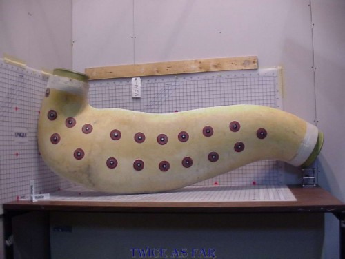
These two photos show the fibreglass unit that formed part of the fourth duct to the fifth zone of the Swissair MD-11 aircraft. This particular unit came from Finn Air. The unit burnt in the FAA burn tests was a second unit and identical to that used by Swissair in their aircraft. This duct has been placed on the 3D grid system, each square being one inch, so it was a very large item. Nothing of the duct from Vaud was found in the crash debris. If any of it failed to burn, then it certainly would have been broken up and much or all of it may have floated away as the debris trail heading out of the crash site was extensive.

This photo shows the 3D grid system that was set up so Garstang's CAD people could redraw the exhibits with their burn areas included. They would take the CAD drawings supplied by Boeing, locate the area of the particular exhibit, and then draw in the burnt areas. The whole thing was very time-consuming but once finished the CAD system helped tell a story. Unfortunately the ability to tell an accurate story was handicapped by the rules and regulations of the TSB to such a point that much physical evidence was ruled out, while ruled in was much conjecture and unsubstantiated opinion. "Why investigate when we can speculate?"
The exhibit duct in this photo it is a foam-like material but firm. The button objects on the surface are fasteners for metal rods that pass through to the opposite side of the duct, and they provide its stability and strength. This particular duct was received from another airlines company and is somewhat different to that used by Swissair. The Swissair duct had a more wood-like looking finish and was coated with a varnish or lacquer material that was flammable under high heat.
| ------------ SITE MAP ------------ |
* * * * * * * * * * * *
MELTS ON CLOTHING
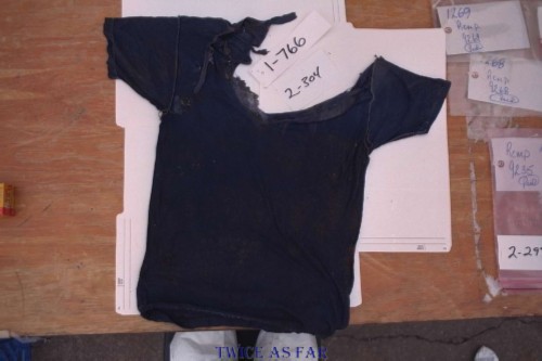
This photo is of a T-shirt retrieved during the first month of the investigation.
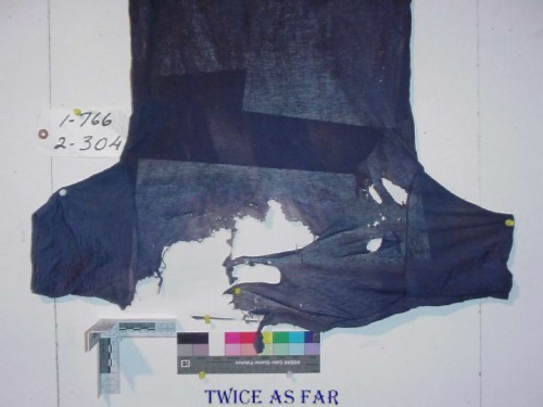
Later the shirt was systematically photographed and documented to show the burn areas and to differentiate between burnt areas and those of mechanical damage.
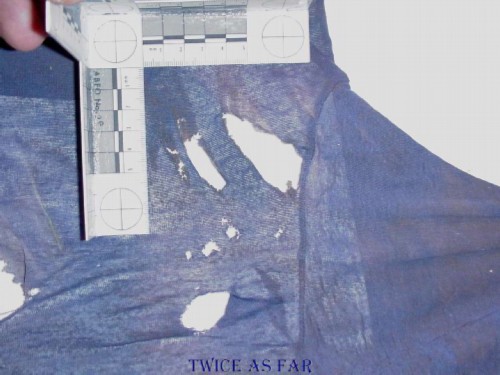
A photo showing one area at the sleeve joint with a centimetre scale.
A close-up of the same area with the centimetre scale adjusted a bit closer to the burns. The discolouration and edges indicate heat. The shirt appeared not to have been worn at the time of being damaged and was likely in carry-on luggage.
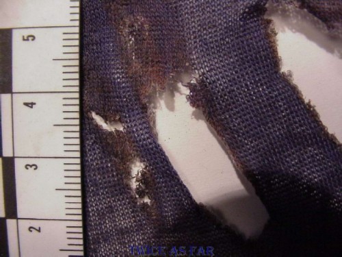
This closeup is another portion of the shirt with mechanical damage and a piece of swarf, a spur that results when drilling metal. The location of the shirt pre-crash was never determined and where the swarf came from is not known.
This is a picture of 'swarf' on one of the beams in the forward 'E & E' Bay of one of the aircraft under refit. Because so much work is done on the aircraft during a refit or a 'D' check, they cannot help but create this type of material. However, before finishing, the last job is to clean up the mess including this material. While it may be in a harmless position at the moment of taking the photo, one sudden drop in altitude while flying can put this material into a bundle of wires where it can vibrate and chafe the insulation.
| ------------ SITE MAP ------------ |
* * * * * * * * * * * *
ON-BOARD FLARES
Dr. Brown's email of clarification that was received just after the 'change-the-notes' meeting mentioned that he had requested information about onboard flares. This photo shows the 2.1 or right forward door of the aircraft during the refit with the inside covering removed. This allows one to view the emergency descent slide that is attached to the door. Inside that slide are emergency supplies including flares. However, this equipment, stored inside the door, is well below ceiling level and would have been outside the reach of the fire that was immediately overhead in the above ceiling area. The flares could not have been a source of the magnesium in the short-circuited beads that Dr. Brown had found with the AES equipment. There is no provision for any flares to have been stored anywhere in the overhead area. No fire damage was found near the forward evacuation slides.
| ------------ SITE MAP ------------ |
* * * * * * * * * * * *
MY CAMERA EQUIPMENT
By adding a ring light flash unit to the Nikon F70 system, a greater depth of field could be obtained when photographing the small short-circuited wires. This one being photographed was a short wire that was less than one inch long. But it was the wire melt that was the object of the photo, not the whole wire. The use of bellows and a reversed 28 mm lens allowed for nearly three times magnification with sufficient light for a small aperture to provide a maximum depth of field.
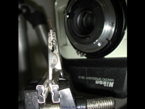
Each wire was held between heavy gauge paper as shown in the jaws in this photo. That ensured there would be no damage to the wires from the jaws of the clamp Of course, the camera equipment was Nikon.
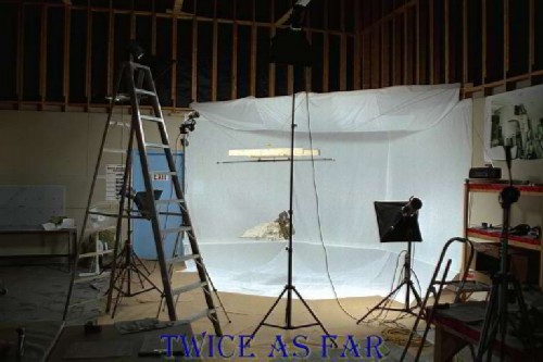
This image is a view of the photo studio that was set up in the backroom of the hangar, ironically room #111 of the hangar.
The studio lights were obtained as surplus equipment from the Canadian Police College Forensic Identification Training Unit. It was a mere paper transfer, and the minimal costs were picked up by the Transportation Safety Board. The lights replaced normal battery operated flash units. Replacing those units saved nearly fifty dollars per day in batteries and allowed the time required to photograph an exhibit to be reduced from an hour to five minutes. Both Gorman and Lathem severely reprimanded me for obtaining the lights without going through the correct administrative process, a system that would have taken months to complete. This studio setup with these lights was used to photograph hundreds of exhibits and saved many thousands of dollars in time and expenses.
The camera is positioned high up on the tripod to take a look-down series of object model photos of the exhibit hanging from the swing. Using a white background eliminated the need to edit the final photos to isolate the exhibit image from an unacceptable background. Thirty-six photos were taken at each of three camera elevations. For each photo, the exhibit was turned ten degrees.
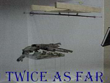
This is the studio setup used for taking the object model photos required for the MD-11 tour program. After various trials, it was determined that white sheets were the best background to use. This photo shows one of the first swings in place supported by ropes. It consisted of a wooden support platform with a rotating metal pipe below it from which strings hold the exhibits to be object modelled. Eventually, the unit would become two pipes in a cross-pattern configuration so that larger exhibits can be rotated. Many of the objects photographed became groups of exhibits assembled as one exhibit, as is the case in this photo. The purpose for all this was to allow investigators worldwide to view the many thousands of exhibit pieces from a computer instead of having to access the exhibit.
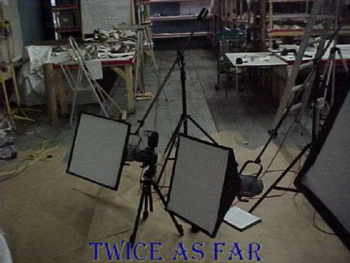
The low angle position for the camera was nearly as difficult as the high angle. Each photo of the exhibit had to be properly framed in the viewfinder. Remember that 35mm cameras did not have a multi-position digital screen.

The FDCM (Forward Drop Ceiling Mock-up) consisted of several tables put together to represent the forward ceiling area of the aircraft. This included the forward portion of the first class area, the area above the three galleys and two lavatories at the forward doors, and the overhead area of the cockpit. This consisted of an electronics housing space in the overhead ceiling area between the two pilots that was called the bathtub. It was a fibreglass structure that resembled a bathtub. On the exposed lower surface were the overhead controls, switches, and wires that could be easily reached by either pilot. Three times the table was photographed and each time, exhibits were found to be either out of position, too long or too short, too high or too low or just not present. On the last effort, a boom truck was brought in to allow the mounting of flash units and the camera in the boom's cage as shown in this photo. Also in the photo in the top right area can be seen the four additional flash units hung from the ceiling as fill lights for the table photos, and the covers that were placed over the hangar windows to control exterior sunlight.
* * * * * * * * * * * *
| ------------ NEXT PAGE ------------ |
| ------------- SITE MAP ------------- |
| ------------ Home Page ------------ |
![]()
![]()
![]()
![]()