
_svg.png)
TWICE AS FAR

SWISSAIR 111
CRASH INVESTIGATION
![]()
![]()
![]()
- THE INVESTIGATION -
THE DEBRIS RECOVERY CONTINUES

A scallop dragger was the next method utilized to recover
the debris off the seafloor, nearly two hundred feet below.
A dragger utilizes a heavy chain mesh that is dragged across the bottom
to entangle the target material.

At the end of each pass, the drag is pulled up so that the
trapped debris could be removed.
Hundreds of passes were made.

As can be seen, not only aircraft debris was retrieved.
Heavy rocks accompanied much of the material.
What is unknown is how much material was caught in the chain mesh, only
to come free as it was being pulled to the surface at the end of the pass while
the boat was positioned outside of the retrieval zone.
What’s more, how much material was dragged into positions between large
boulders and then covered or wedged so that later vacuuming failed to retrieve
it.

The retrieved material was placed in plastic fish tubs to
be off-loaded at Shearwater and then sorted on the hangar sorting line.
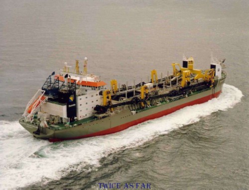
THE QUEEN OF THE NETHERLANDS
The last stage of the debris recovery was the vacuuming of the seafloor. The Queen of the Netherlands was used to conduct that phase as it has been called 'the world's largest floating vacuum cleaner.'
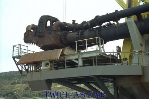
This photo shows the drag head, the piece of equipment that trails along the ocean floor to dislodge and suck up the material being vacuumed. It is six metres or nearly twenty feet wide. After travelling more than two hundred feet inside the connecting pipes to the ship on the surface, the material is then stored in three large holding tanks to be later discharged on shore.
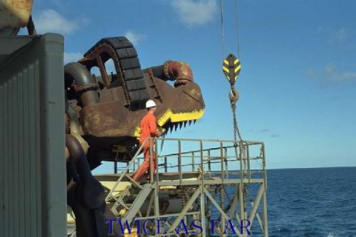
The other side of the unit with one of the ship's crew for a size comparison.
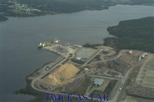
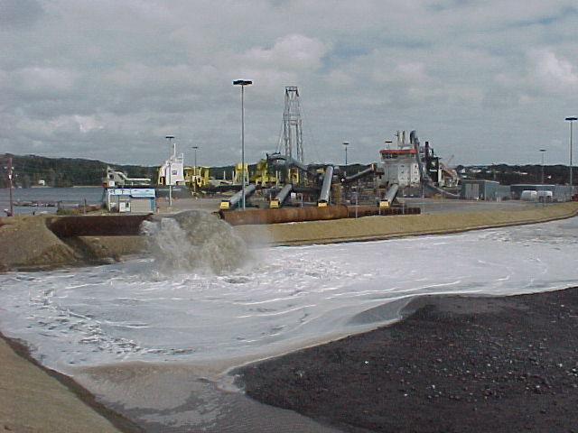
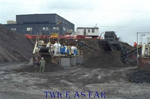
This image is an aerial view of the Sheet Harbour area with the Queen of the Netherlands docked and discharging her contents. One of the problems encountered was to find a location where this could be done. Canadian laws prohibit the return of the debris to the seafloor even though it was natural material from that location. So a suitable location had to be found where the material could be off-loaded, temporarily stored, examined, and then buried. Sheet Harbour had a facility that met those requirements. The holding pond for the discharged material is located in the centre of the photo.

A secure pond area was created for the huge volume of water and debris that had been retrieved. When the Queen of the Netherlands came into Sheet Harbour at high tide, the ship's sounders indicated only six inches of clearance under the keel.
In this photo the debris mixed with water is being pumped into the far end of the holding area. The debris is then allowed to settle out while the excess water leaves via the outlet at the opposite end. By this time none of the debris was of the floating variety so it quickly settled to the bottom.
The off-loading begins by pumping the debris laden water from the ship through piping to the holding pen.
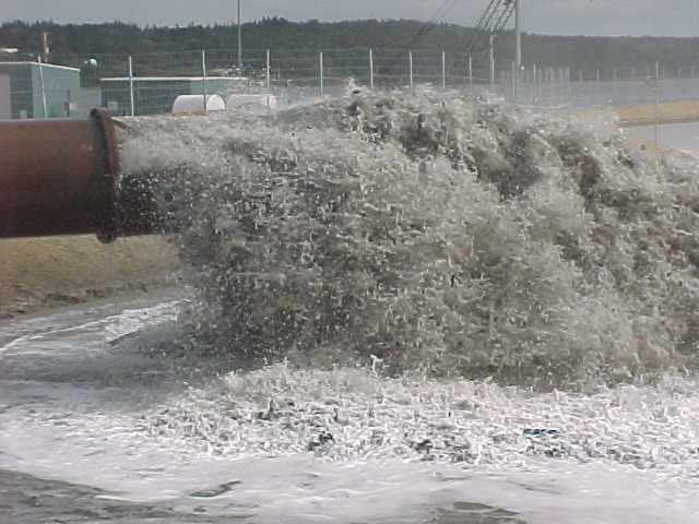
As can be seen, there was nothing gentle about the process.
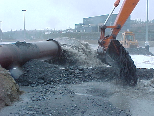
Due to the volume of debris material and sediment retrieved from the ocean bottom, the use of heavy equipment was a necessity. Fragile pieces of wreckage took a severe beating.
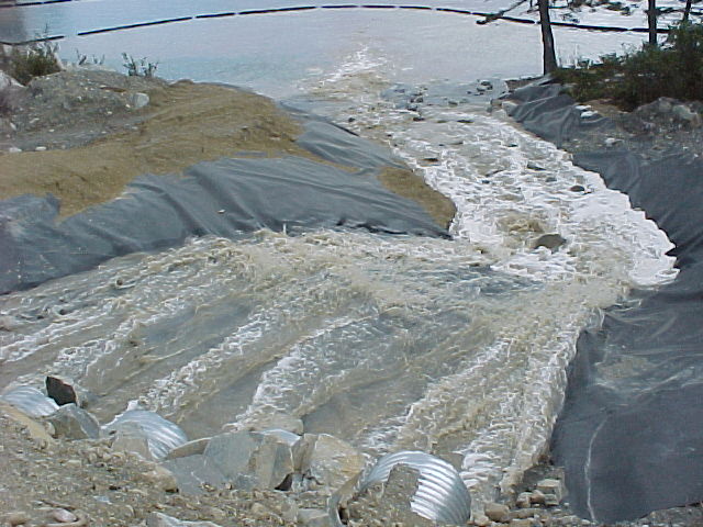
This is the run-off of the excess water. The heavy debris had settled to the bottom of the holding area before reaching this point. Of the lighter materials, it is unknown how much might have been lost.
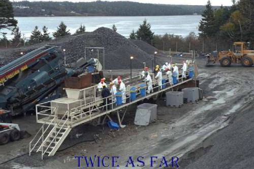
Once the water had drained off, the debris had to be sorted. A gravel sorter was used to eliminate the rocks and large items, but this left the tonnes of smaller debris that had to be hand sifted by a line of human sorters.
Of interest was the fact that the time estimate for the processing of the 8500 cubic meters of sand, dirt, and debris was at least four to five weeks. The TSB allocated three weeks, and it was completed in that time. How much material bypassed the sort line and went directly to the disposal site is unknown. No time was wasted in washing stones to determine if they were diamonds, or looking for lumps that under their covering of mud might have been molten evidence of an incendiary device.
From a forensic point of view, whenever a large plane crash occurs there is always a loss of evidence due to one factor or another. A crash on land usually results in a fire that consumes much of the evidence. When it lands in the ocean, a large quantity of material floats away. What settles to the bottom must be retrieved, depending on the depth of the site. In this case, the crash occurred in waters shallow enough to allow retrieval, but it was suspected that by using a trawler and dragger equipment, some of the materials had been moved outside of the planned vacuum area. Due to the limited capacity of the ship's holding tanks, those items were never retrieved. The majority of the collected material was the hundreds upon hundreds of tonnes of mud, sand, silt, rocks and other materials including sea life. This collection all had to be sorted.
One of the big questions was if the diamonds, now worth nearly half a billion dollars, were on board. After looking at this photo can anyone honestly say that tiny mud covered diamonds can be sorted out of this mess? What about physical evidence of an incendiary device that was possibly a blackened and molten piece of some unknown material?
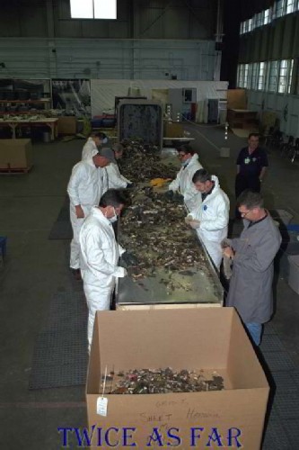
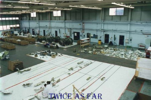
This view is of the hangar sorting line showing the debris from Sheet Harbour. What can be seen here is typical of the size of the pieces that had to be examined. Numerous boxes containing this type of material were retrieved, and some valuable evidentiary material was found. It may be noted here that whenever this sorting process was underway, a video camera recorded the entire process.
| ------------- SITE MAP ------------- |
* * * * * * * * * * * *
FORWARD EMERGENCY BATTERY BOX
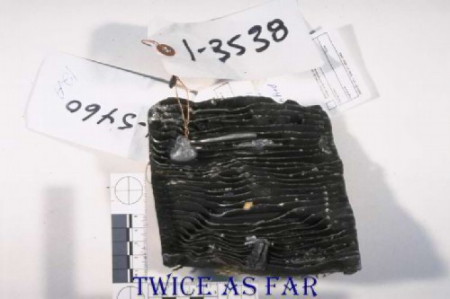
One item of importance was a quantity of molten aluminium that had been located early in the investigation. A large molten mass had solidified in the fins of the forward emergency battery box. Its existence indicated high heat above that area. The scale ruler is in centimetres.
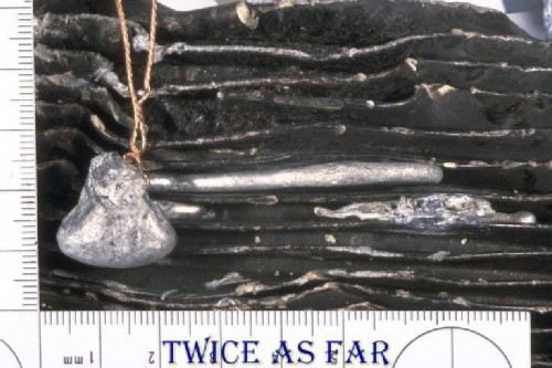
The pendant, as it was called, is seen here in position in the battery box fins. It turned out to be a potential key to some important questions. It was hoped that the molten aluminium had captured evidence to determine if the oxygen line that led to the flight crew's oxygen masks had leaked. If AES examination could reveal higher than normal levels of oxygen, then it would indeed mean the line had leaked which in turn would have influenced the fire during that period. Note that the copper wire leading to the photo's top edge is the tie for the exhibit tag.
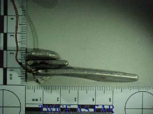
This photo shows the pendent from the underside, and the 1 to 5 scale is centimetres. 2.54 cm equals one inch. It is evident by the amount of solidified material that the aluminium was in its liquid state for a considerable period instead of microseconds as in the case of a short-circuited copper bead. Also, the aluminium must have flowed freely upon itself, thus negating the value of Sieverts' law and Dr. Anderson's theory.
One thing that had to be considered was that a fire must have been ongoing at that point to create the heat that melted the aluminium, so would the higher oxygen levels show up? Ultimately it became a question of which came first. Was it the oxygen line leak that enabled the fire to melt this aluminium, or was this aluminium the by-product of the intense fire? Might that fire then have melted the aluminium end cap of the oxygen line thus allowing an even more intense fire in the cockpit ceiling area? The fire damage to the ceiling materials in the cockpit tends to indicate the latter, that the line ruptured just before the crash and indeed its rupture and the loss of oxygen to the pilots was likely the final event that led to the crash.

This photo shows the interior of the battery box. The unit is sealed when in position and from the appearance of the insulation on the wires and other flammables within the box, this was not the source of the fire. This fact had already been determined at the time of the New York trip, and it was certain that the batteries within this box had not given off flammable gases to become the cause of the fire. That question was raised during that meeting, thus creating a needless discussion. It was then mentioned again in the trip report as a potential event.
One of the problems with the theory of the end caps and elbows of the ducts burning away and allowing fresh air to blow into the area just aft of the smoke curtain is the fact that the forward emergency battery box suffered no indication of excessive internal heat. While aluminium dripped onto it and high levels of heat caused that to happen, the battery box itself appeared to have suffered no internal fire damage, and indeed paper labels and wire insulation inside the box remained unburnt. While it is most likely that the end caps and elbows did burn off, that may have happened after the ventilation system had been shut down as indicated by the cockpit data recorder.
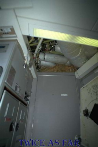
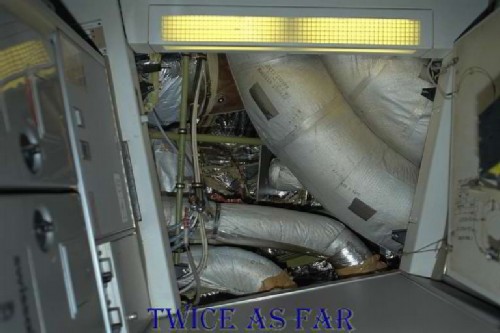
This photo shows the location in the aircraft of the forward emergency battery box. The door at the lower centre of the photo allows entry to the flight deck or cockpit. On each side are the forward galleys, and overhead is the area of the smoke curtain. In the bottom right corner can be seen a black box, this being the forward emergency battery box, fixed to the overhead hatch.
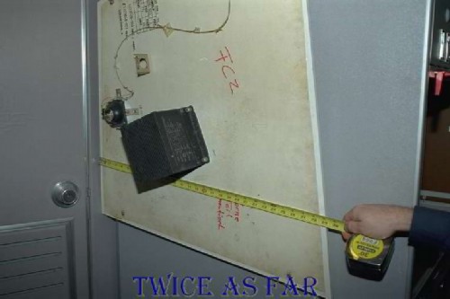
This photo shows the hatch still in the same position with the battery box at centre. When the hatch is closed, the battery box is on the top side hidden from view and nestled in a void between the ducts.
This photo shows the opening with the door to the flight deck at the bottom of the photo while the hatch and battery box are on the right. The battery box fits nicely between the insulation covered ducts. The dull grey colour of their covering indicates Metalized Tedlar, the non-flammable version. At the centre of the photo can be seen an aluminium plate on edge, what is called a disconnect plate. This plate is likely the source of the aluminium that formed the pendant. It is possible that when the duct end caps burnt off, fresh air was fed to the flames which intensified the fire at that point thus melting the aluminium plate. However, since the flammable end caps were covered in non-flammable Metalized Tedlar, what caused that covering to burn thus exposing and allowing the end caps to burn?
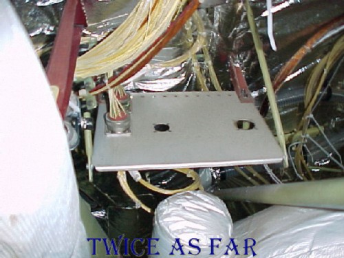
A closer view turned 90 degrees clockwise to the previous photo showing the disconnect plate with the blocked end of the duct below it in the photo, or in reality, directly behind it. Once the Metalized Tedlar, material that doesn't burn in a normal fire, burnt off and the plastomeric end cap then burnt, fresh air from the recirculation system would then have blown into the area likely fanning the flames sufficiently to melt this plate. However, something had to have been very hot to cause the Metalized Tedlar to burn.
| ------------- SITE MAP ------------- |
* * * * * * * * * * * *
JET ENGINE RECOVERY & EXAMINATION
JET ENGINE RECOVERY & EXAMINATION
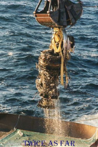
This photo shows the retrieval of one of the jet engines from the ocean floor by the crane and clam bucket of the Sea Sorceress. What normally is a marvel of human engineering is now just so much junk metal. However, even in this state, the engines had a story to tell. The Pratt & Whitney engineers along with Elaine Summers of the TSB were able to decipher that story to show that the engines were not the cause of the crash.
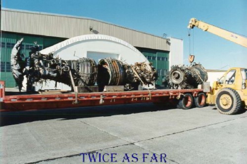
The three engines together are large enough to fill a flat bed trailer. The engine being hoisted by the crane is the #3 engine or the right wing engine. It has the bent shaft due to the force of the initial impact with the ocean. The middle engine on the flatbed is the #1 engine or captain's left side engine. The #2 engine or tail engine was in a windmill condition in the last stages of the flight. The engine had been shut off, and the fan blades were turning merely due to the flow of the air that rushed over them. The #2 engine is positioned at the front of the trailer, and it can be seen that the fan blades suffered the least amount of damage.
The three engines are positioned on the hangar floor just left and above photo centre. Examinations were conducted of all three. Each engine has a controlling computer system called FADEC. Two of the three were retrieved to reveal that they had lost contact with the plane's engine control system once the fire burnt off the connecting wires. The three units normally 'talk' to the aircraft's system twenty-five times per second. Because of that inability the two engines remained at their last setting for nearly ten minutes. The settings were sufficient for the aircraft to maintain flight and manoeuvre for a landing. The tail engine had been shut down and was in what was called the windmill condition. Had the plane been able to land at the airport, the problem would then have been shutting down the remaining two engines. This likely would have been accomplished by means of the emergency fire control system. It is a non-electronic system and consists of levers and cables on pulleys under the flight and passenger decks to set off the fire extinguisher system in each engine.
As for the amount of onboard fuel, it was determined that the crew had indeed been able to dump at least some fuel. But the system is designed to retain seven thousand pounds of jet fuel which was more than sufficient for the aircraft to fly to the airport at Halifax.
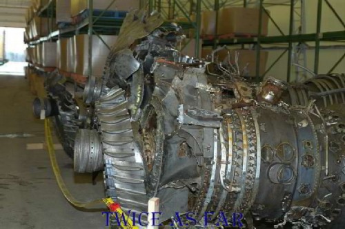
This photo is a close-up view of the #1 engine while in storage in J Hangar.
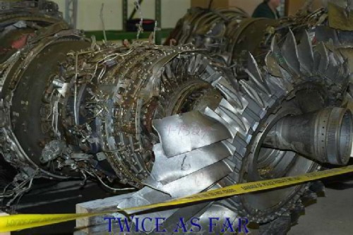
A close-up view of the #3 engine with its bent central shaft while in storage in J Hangar.
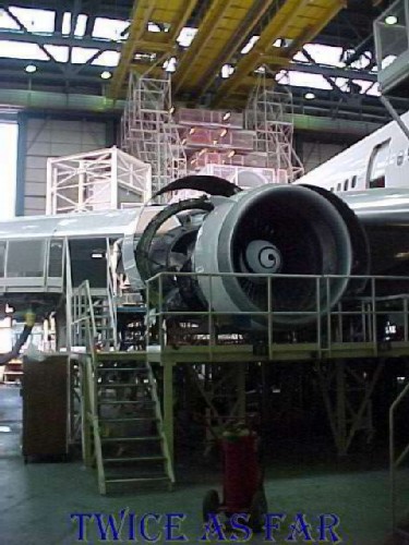
The #3 engine of the aircraft that was being repainted in Zurich. This provides some perspective as to the size of the engine considering the platform is eight steps up, or about two meters (6 feet) high.
* * * * * * * * * * * *
| ------------ NEXT PAGE ------------ |
| -------------- SITE MAP -------------- |
| ------------ Home Page ------------ |
![]()
![]()
![]()
![]()