
_svg.png)
TWICE AS FAR
SWISSAIR 111
CRASH INVESTIGATION
![]()
![]()
![]()
- THE INVESTIGATION -
THE THIRD ZURICH TRIP
INSULATION BLANKET REMOVAL
By the time of this crash, the airline industry had already been told to remove the Metalized Mylar that covered many of the Boeing aircraft's insulation blankets. The material had been found to be very flammable at normal fire temperatures. The question raised by John Garstang was whether or not the replacement material was just as flammable in an environment of short-circuiting wires. Was one problem being replaced with yet another?
It was decided that the insulation blankets removed from the Swissair aircraft would be collected for a later series of burn tests. At the same time, photos of the equipment and bare aircraft could also assist in the investigation.
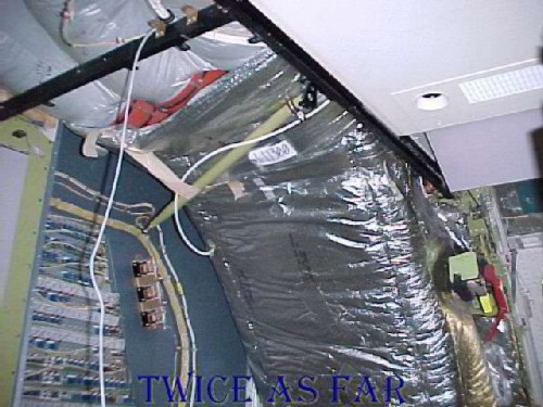
This photo shows an area of three ducts that are called the Queen Mary ducts. They are located just ahead of the right forward 2.1 door and are a major part of the air circulation system in the aircraft. This photo shows that the ducts are wrapped in an insulation material, the photo having been taken after the removal of the right forward galley unit. The three separate ducts can be seen in the top left corner wrapped in the grey Metalized Tedlar insulation. Then an outer wrap of shiny insulation material can be seen in the lower area. The Boeing people who were present for the blanket removal process quickly realized that this outer wrap was not the same Metalized Mylar that had to be removed, but it was made of another series of Mylar that was much more flame resistant. Later tests showed that it would not maintain a flame front that would enable it to burn under normal conditions.
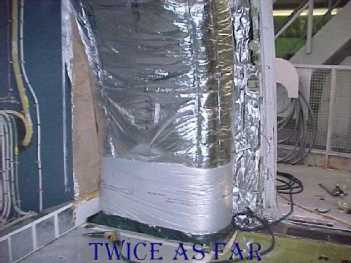
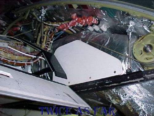
This photo shows the bottom area of the Queen Mary ducts and the right forward 2.1 door. The wall on the photo's left is the back side of the aft cockpit wall. On the other side of that wall is a fuse panel.
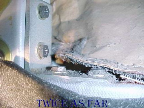
The area shown at the bottom of this photo is the top of the door frame for the right forward or 2.1 doorway to the aircraft. Looking through the door, the viewer can see a metal staircase and railing of the working area just outside of the aircraft. This forward door is of the type that raises and lowers on two tracks with a cable attached to a motorised drum system on each side. The door, now removed, rolls in the two metal tracks of which the forward track can be seen as the green painted strip of metal from a quarter of the way up the left side of the photo to the top left corner. The white and black horizontal material foremost at the photo's centre is a piece of ceiling frame that guides the flow of wires from the forward fuse panels on the left towards the rear of the aircraft to the right. To the left side of the photo and below the horizontal black and white ceiling piece can be seen one of the drums that turn to operate the door cable and thus lift and lower the door. A sheet of thicker blue-green rubberized-like material is positioned to cover and protect the relatively fragile material in the doorway's overhead ceiling area. This cover is present on both sides of the aircraft at the two forward doors. Later burn tests of this material proved that it was non-flammable at normal fire temperatures. The track on the left is the same track that on HB-IWF was found to have suffered extremely high heat thus causing it to bend and part of it to melt.
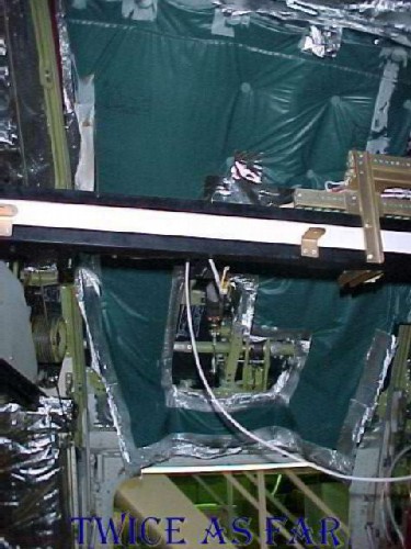
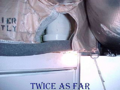
This photo shows the edge of the Queen Mary ducts beginning at the photos right
of centre and heading into the photo's
centre. This view is from the door opening in the previous two photos.
The wheel and cable system, one of which is visible
on the right side of the
photo, is the mechanism that raises and
lowers the door. The door track can be seen going across the top of the
photo and is the location for the debris
track that was found to be bent and twisted due to the extremely high heat as
well as having the 'broom straw' molten metal. Just left and above centre
is the electrical cable run position
called the ‘waterfalls.' The wires
come out of the tubes that can be seen capped with
a reddish-orange wrap and they drop down
to the piece of ceiling frame that guides and protects their route towards the
rear of the aircraft located back over the viewer's left shoulder. The
black metal strip left of photo centre and angling up to the left is the door
deflector that is in a position to guide
the door flap as it raises/lowers and to ensure that it does not interfere with
the electrical cables. One of the concerns was the possible contact
between the door cable and the electrical wires since the cable moves up and
down to raise the door. No evidence of contact
was seen on any of the MD-11's that
were examined.
The space through which the area
is now seen
is usually covered by a piece of ceiling tile.
Its
thickness at these two forward doorways is unique within the
aircraft, and thus a piece of it can
be positioned at either of the two forward
doorways. Two small pieces of this thin
material were found to have burnt extensively.
The estimate was that the tiles had burnt for five minutes at 1700 deg F or ten
minutes at 1100 deg F. Considering the non-flammability of the adjacent
Mylar material of the Queen Mary ducts, the ceiling cover in this area, and the
lack of any other substantial fire load in this immediate vicinity, one has to
question what was burning for so long at such a hot temperature.
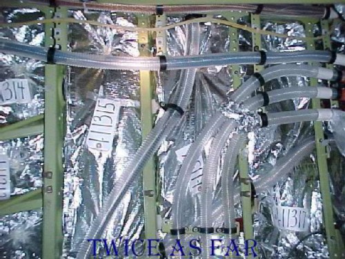
This photo shows the right side of the same doorway 2.1, or the right forward door of the aircraft. Metalized Mylar covered the main insulation blankets that were behind the right forward first class lavatory and that are still in place. These blankets have been tagged with their exhibit numbers, one being visible as the white tag with the 1-11311 marked on it.
The exhibit numbering system set up for the aircraft reconstruction hangar was simple. Aircraft related exhibits belonged in the 1- series beginning at 1-1 and going all the way to 1-11311 as shown here. In total there were more than 18,000 numbered exhibits. Whenever one exhibit was divided for a purpose such as a burn test or other analysis, the original retained the initial exhibit number while the new piece was given the next available sequential number. So if a sample was later taken from this blanket 1-11311, the next number available might have been 1-15000. To simplify things even more, if an item was constructed out of numerous previously numbered exhibits, - sometimes as many as one hundred or more exhibits - it was given a new single exhibit number. All the other exhibit numbers were added to its description in the computer.
The morgue numbering system, set up by Insp. Lee Fraser was entirely different and too convoluted even to describe here other than to say it utilized groups of both letters and numbers in various sequences depending on its stage of processing. There is always need to keep these systems simple. Too many problems can occur when mistakes are made while transcribing complicated numbering systems after long tedious hours of work. The morgue system showed just how little experience Lee had when it came to major file investigations. Today, I hope that a computerized barcode system would be utilized that would simplify the recording process.
Once the main blanket covering is removed, what remains are the individual smaller blankets that fit between the ribs of the aircraft, or stringer in Boeing terms and longeron in Swissair jargon. Here the main covering has been removed, and the smaller pieces are marked with exhibit tags. The blankets are simply two layers of Metalized Mylar material sealed on all four sides to encase a fibreglass insulation bat. The only actual difference is the size. So in effect, there is a double layer of fibreglass insulation with four layers of Metalized Mylar.
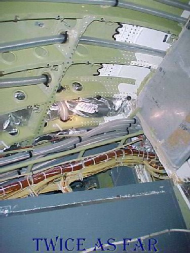
Once everything is removed there remains the painted inside surface of the aircraft skin. In this instance, some of the skin has been painted white, and two blankets are still in place. During initial construction, the insulation blankets are installed first, and then the wire runs pass through holes created in the blankets. The insulation bats must be sealed to eliminate the absorption of water during the flight. Water absorption would drastically reduce its insulation value and add considerable weight to the aircraft besides causing mould. Information from Swissair revealed that during a normal flight as much as 500 kg or litres of condensed water is retained on the overhead material surfaces. Also in this photo one can see a bundled wire run, and how the white nylon ties are closely spaced to maintain the bundle's integrity.
| -------------- SITE MAP -------------- |
* * * * * * * * * * * *
SHORT CIRCUIT ON A GALLEY UNIT
SHORT CIRCUIT ON A GALLEY UNIT
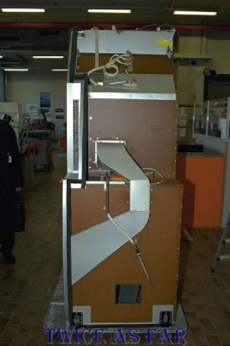
During the refit of HB-IWN, the #9 galley was removed to reveal an old short-circuited wire incident. The wire had shorted out during a previous flight but had not caused a fire. It was repaired in place and continued in use by the original airline company. After Swissair had bought the aircraft, they found this short when the galley unit was removed. Shown here is the galley's back surface or the surface usually against the wall of the aircraft. At the very top is a grey coloured strip of metal. At its top edge and just left of centre can be seen a small area of dark discoloured paint. It is just below the centre light of the three ceiling lights at the topmost of the photo. The next photo shows a closer view of this area.
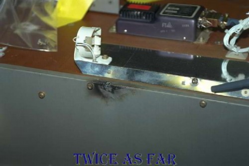
This photo is a higher angle and closer view of that same location on the grey strip of metal. A short circuit has occurred at the corner of the grey painted metal, just to the left of the photo's center.
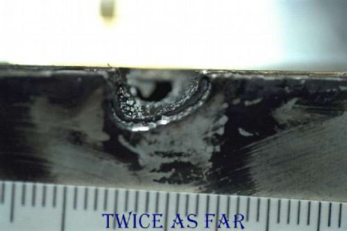
This photo shows a close-up view of the soot area. It reveals that the aluminium metal has been damaged by an actual melting and burning of the corner of the aluminium alloy of the galley unit. The scale is in millimetres. 25.4 mm is equal to one inch. The diameter of the melt area is about 10 mm or approximately 3/8 inch.
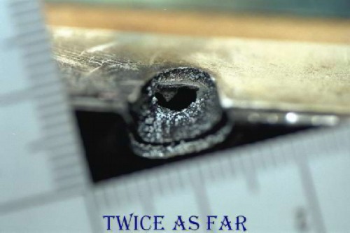
This photo shows the far side of the melt area and the fact that a hole has been completely burnt through the aluminium material. The scale, although out of focus, is still in millimetres.
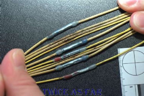
These are the culprit wires that had been repaired and returned to service by the previous owners of the aircraft. They are Kapton insulated wires that serve the galley unit, and five were noted to have required repairs. The remaining five were merely scorched, but the insulation remained intact.
The explanation provided was that during a flight the wires shorted out against the metal of the galley, thus causing it to malfunction. On checking, the service company found the shorted wires and made the repairs even though it was not known how much damage was done to the galley unit or how the short had occurred. When SR Technics took out the unit, they found the damage and made the enquiries to receive this story, plus they now realized that the wires had been pinched and rubbed against the corner of the galley unit. Even though it was Kapton insulation and there had been five shorting wires involved in a very serious incident, no fire had occurred, and there was merely some soot marks on the wall behind the unit.
| -------------- SITE MAP -------------- |
* * * * * * * * * * * *
INSULATION BLANKET LABELS
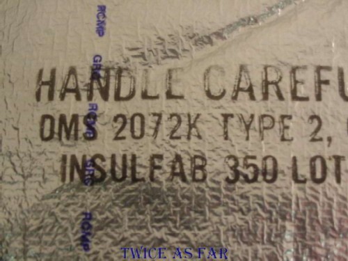
Each of the insulation blankets in the aircraft was marked by a series of stamps to indicate the type of outer covering, date of manufacture, brand name, and lot number. The idea was to try to locate similar material with similar details as the material that had been on HB-IWF. In this case, the material is DMS 2072K Type 2, Insulfab 350 Lot 2012 manufactured on 12/5/89. A fabric design can be seen to be under the silver coloured outer skin. It was there for added strength.
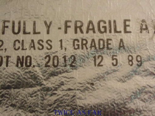
This photo is a continuation of the above stamp.
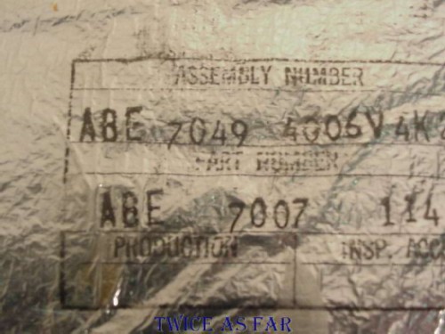
Another stamp was present on each blanket, this being a part number, the assembly that the blanket may be part of, as well as an inspector ID and several other codes for various purposes. Nothing is put in the aircraft unless it is authorized and signed off a person qualified to do so.
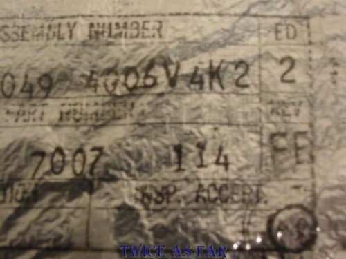
This continuation of the above stamp.
| -------------- SITE MAP -------------- |
* * * * * * * * * * * *
LEAKING SMOKE CURTAIN
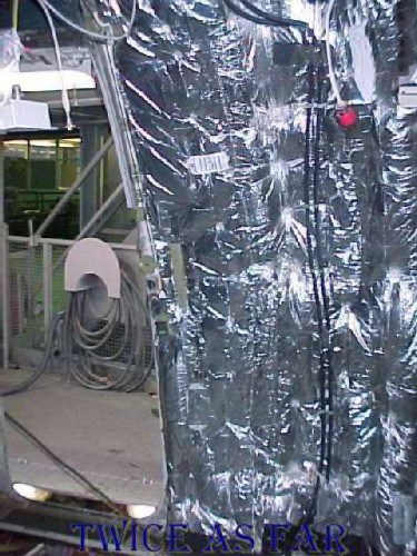
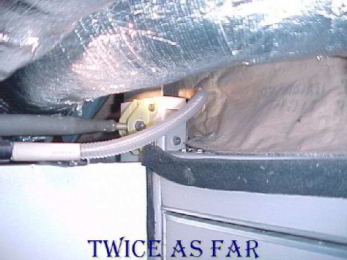
During the third trip to Zurich for the retrieval of the insulation blankets, there was an opportunity to photograph the area that is overhead the flight deck doorway. This area is blocked by the fabric smoke curtain. This photo was taken on HB-IWN while it was under conversion to the Swissair configuration. Here the smoke curtain can be seen above the doorway. It is the brown paper coloured material between the edge of the door frame and what is an air duct at the extreme top of the photo. The galleys that would normally be on each side of the doorway have been removed, as has much of the ceiling.
This photo is taken on one of the other Swissair MD-11 aircraft that was already in normal service and it shows at photo centre a slight gap at the Velcro or hook and loop fastener. This is the area to the upper left corner of the doorway as one looks forward and the unit on the lower left is one of the forward galleys. During the investigation, there was a need to have an idea of the condition of the smoke curtain on HB-IWF at the time of the crash. Of course, it was impossible to determine precisely. However, during the inspections, no smoke curtain was found to be completely closed and most had a gap at least as large as that shown in the photo. Many had even larger gaps. So it was entirely reasonable to assume that the smoke curtain on HB-IWF was not air tight. What's more, the seal was a hook and loop (commonly called Velcro) fastener and that type of seal is not air tight.
The reason for all this was to try to answer where the fire started. The condition of the smoke curtain revealed that the fire could have started in the overhead area of the forward galley and still have smoke first smelled by the pilots in the cockpit. Air movement in that overhead area was shown to have been towards the lower pressure of the cockpit area due to the normal draw of the air recirculation system.
This photo is a close-up view of that opening in the hook and loop of the smoke curtain. It shows a slight accumulation of dust, so the curtain has been open for some considerable time.
This photo is the right side of the same doorway and smoke curtain. It shows a very large opening in the smoke curtain, something that would not impede the passage of air between the two spaces.
| -------------- SITE MAP -------------- |
* * * * * * * * * * * *
HELLA LIGHTS

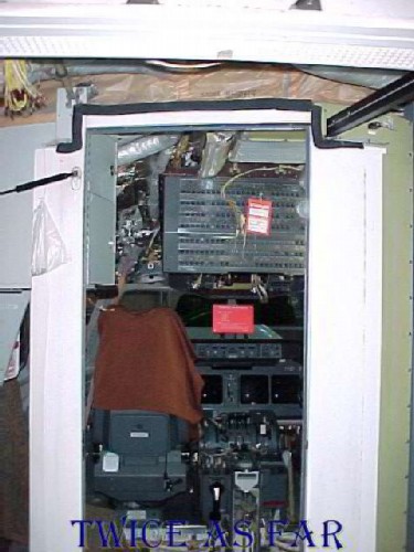
During the investigation, there was a question as to the possible involvement of the Hella Lights as the cause of the fire. If nothing else, they had to be ruled out. This photo was taken during one of the Zurich trips and shows the pilot wearing an oxygen mask while seated in the left hand or the Captain's seat. Directly above his head can be seen what appears to be a handle attached to the ceiling. Just above and to the right of this handle, near the top of the photo, is a black object fitted to the ceiling plastic. This is the Hella light or what in a vehicle would be called a map light. The light can be focused and is directional, and its purpose is to allow the pilot to read manuals or view maps without affecting the ambient light in the whole cockpit. Temperature strips showed that they heated the immediate area behind them to only seventy degrees C.
What is also interesting about this photo is that the pilot is reaching for the manual compass. When the video display terminals are functioning, there is an electronic compass as part of one of the screens. However, a manual compass is maintained that is located just at the pilot's fingertips in this photo. A manual horizon is also present. The bad news is that use of the manual system was not part of the Swissair pilot's training. While it may seem natural for a pilot to use these items, during times of an emergency with extreme stress an individual relies on his or her training to perform what would otherwise be normal functions. If there is no training for a particular function, that function is not used during the emergency procedure. Another consideration was that during the final moments of this flight, the cockpit area would have been dark and filled with smoke that would have made reading those instruments extremely difficult if not impossible.
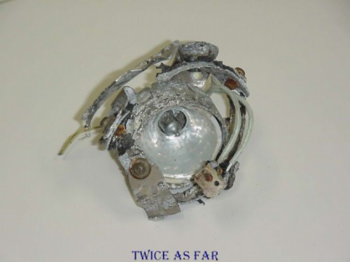
Because of their small size and extensive amount of destruction, they were difficult to locate in the debris. Eventually, the main parts were found. This photo shows the outward view of one of them without the black plastic housing.
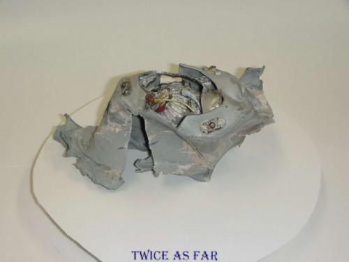
This photo shows the back side of the same light unit.
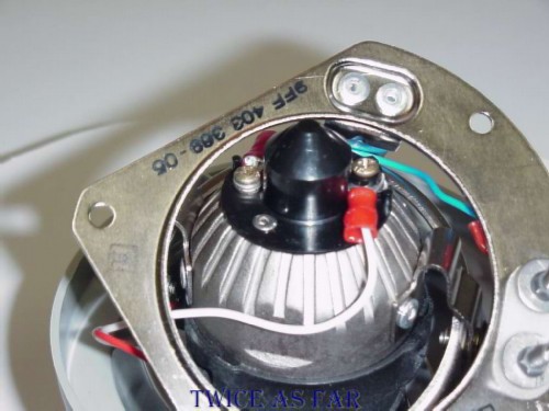
This photo shows the back side of a new exemplar unit showing the mounting ring and the lamp housing along with some of the wires. Tests were performed on one of the aircraft to determine the temperatures reached in the rear area of the lamp when it was functioning. Those temperatures were found not to be extreme and were within a safe range.
* * * * * * * * * * * *
| ------------ NEXT PAGE ------------ |
| -------------- SITE MAP -------------- |
| ------------ Home Page ------------ |
![]()
![]()
![]()
![]()