
_svg.png)
TWICE AS FAR
SWISSAIR 111
CRASH INVESTIGATION
![]()
![]()
![]()
- THE INVESTIGATION -
0THER TESTS
AIR FLOW TEST FLIGHT
AIR FLOW TEST FLIGHT
Part of the investigation included
understanding the airflow patterns in the Swissair configured MD-11 aircraft
while in flight.
Knowing those patterns could help locate the source of the fire.
Boeing's experience in these matters revealed that
airflows in the aircraft while at ground level
differed to those while at high altitude.
One reason for this was that
with the aircraft flying at over thirty thousand feet,
the skin of the aircraft cooled down to minus 60 degrees F.
Plus the plane travelled at a speed of 0.8 mach or about 700 miles per hour,
so any heat on the inside surface of the skin
would quickly dissipate and be lost to the huge heat sink that the aircraft skin had become.
To determine these patterns
there was a need to schedule a test flight with the appropriate systems in place
to record those internal air flow patterns while at altitude.
As mentioned in the book,
there was considerable opposition to having a police investigator on board the flight.
That opposition not only came from Boeing and the TSB
but from RCMP file supervisors.
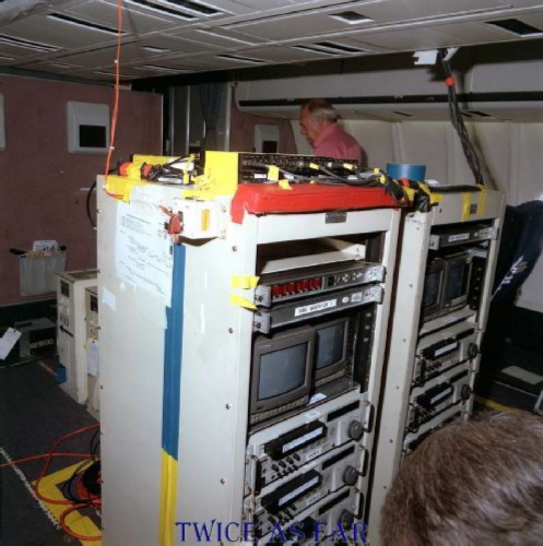
This photo shows some of the video recording gear that was used on the test flight. VHS was the standard for the time as digital recording was still in its infancy.
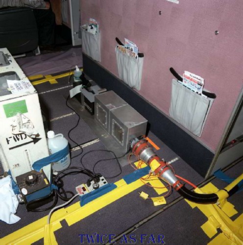
Some of the smoke generating and accumulation gear that were used on board the test flight.
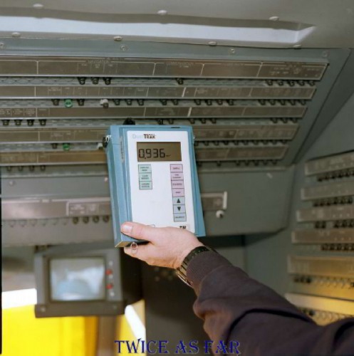
One of the scanners that were used to determine the level of smoke, in this case, in the cockpit area. Several were used, and each had been properly calibrated before the flight.
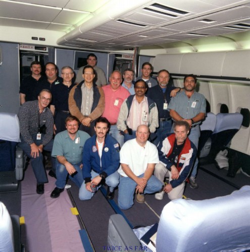
Once the flight was over and back on the ground, there was time for a group photo of those who had worked the test flight, except of course for the second Boeing photographer who took this photo. Four TSB members are present along with me, and the rest are all Boeing personnel. John Garstang is at the photo's left rear with Mark Clitsom beside him and then Vic Gerden as the third from the left of those standing. Larry Fogg is in the blue, white and red jacket and kneeling on the right of the foreground row. Jim Foot is standing at rear centre, fifth from the right of those standing just behind the salmon coloured shirt. I am at the extreme rear of the group, left of centre and behind Gerden's left shoulder, a head above everyone else.
SMOKE INSERTION POINTS
|
Pt # |
Details |
|
1 |
Behind avionics circuit breaker panel |
|
2 |
Above emergency battery pack (sta. 403) |
|
3 |
2.1 (1R) door vicinity of door ramp deflector (sta. 428) |
|
4 |
1.1 (1L) door forward drop ceiling support post (sta. 428) |
|
5 |
Inboard of Lav B at ceiling support post (sta. 477) |
|
6 |
Inboard of Lav A at ceiling support post (sta. 477) |
|
7 |
E & E bay near throttle cable drop. |
|
8 |
Above cockpit door at emergency battery pack panel with handheld dragger tube. |
The tests were completed first with the smoke curtain sealed
and then with the curtain opened.
CAMERA POSITIONS
|
Pt # |
Details |
|
1 |
Smoke insertion point 1 |
|
2 |
Smoke insertion point 2 |
|
3 |
Smoke insertion point 3 |
|
4 |
Smoke insertion point 4 |
|
5 |
Smoke insertion point 5 |
|
6 |
Smoke insertion point 6 |
|
7 |
Smoke insertion point 7 |
|
8 |
Above ceiling cockpit bulkhead |
| 9 |
Above ceiling engine fire S.O. cable drop |
| 10 |
Below ceiling overhead avionics C/B panel |
| 11 |
Roaming cameras |
| -------------- SITE MAP -------------- |
* * * * * * * * * * * *
ALUMINIUM DROP TEST
This video shows the Aluminium Drop Test on ceiling tile and carpet flooring
that took place in the Transportation Safety Board Lab in Ottawa.
It shows molten aluminium at 1000 degrees F
being dropped on ceiling tile and flooring carpet from the debris wreckage.
| -- ALUMINIUM DROP TEST VIDEO -- |
| -------------- SITE MAP -------------- |
* * * * * * * * * * * *
EXPLOSIVE WIRES SALT WATER FLOAT TEST
EXPLOSIVE WIRES SALT WATER FLOAT TEST
The following is a video of the tests that John Garstang and I performed
to see if the explosive wires that had been found on the beach close to Halifax
could have floated there in salt water.
There was no indication that explosives had been involved in the downing of the aircraft,
but to cover all the bases, it was agreed that the test should be conducted in actual salt water.
Remember that things may float in salt water
yet sink in fresh water due to the difference in buoyancy between the two.
So the test was conducted at Lawrencetown beach, Nova Scotia.
It was found that the blue and white plastic exhibit did float,
but the others did not.
Because they were all found together,
it is reasonable to assume that since three of the four exhibits did not float to the location where they had been found,
then neither did the fourth.
No other similar exhibits were found anywhere else during the beach search.
While the explosive wire issue was merely a side show and not related in any way to the onboard fire,
the matter serves to show how the TSB handled potential criminal matters.
If they reacted in this manner over something totally unrelated to the investigation of the fire cause,
then one can easily believe their denial of Dr Brown's AES results
that linked an incendiary device to the cause of the fire.
| ------------ SITE MAP ------------ |
* * * * * * * * * * * *
SEAWATER TEST WIRES
RETRIEVAL RESULTS
During the Auger Electron Spectroscopy (AES) testing of the debris short circuited wires,
Dr. Brown requested that new sample wires be created as a known test series.
The main purpose was to determine what would happen to short circuited wire beads
under various controlled conditions.
Various types of aircraft wire samples were created
according to a prearranged plan
and submerged in seawater for thirty days.
These photos show those wires upon retrieval after thirty days of exposure to seawater.
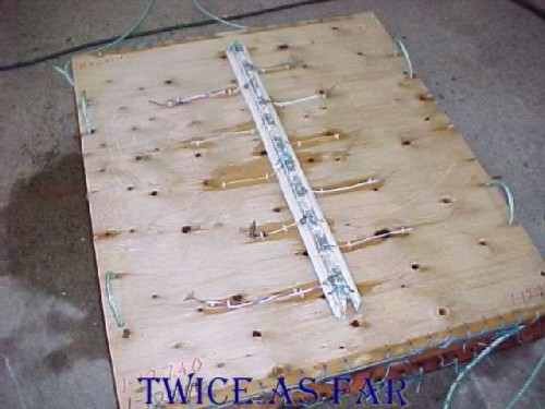
Exhibit #1-12740 is the pallet containing the aluminium frame piece with the attached wires.
It was retrieved after thirty days of seawater submersion, as were the other two pallets.
The pallets had not drifted, and everything on them was intact upon retrieval.
The only thing changed was that the ballast weights were cut out when lifted to the side of the boat.
This allowed for a lighter pallet when it came time to lift them up onto the wharf.
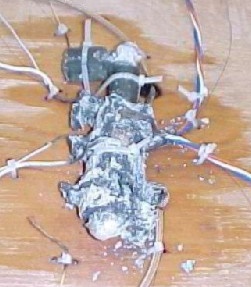
Exhibit #1-12741 was the pallet with the aluminium frame piece and the magnesium rudder pedal.
Again everything was intact, and the wires were still in contact with the magnesium pedal.
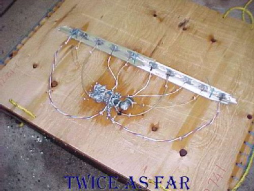
The rudder pedal had deteriorated only slightly
during its thirty day submersion.
Pallet exhibit #1-12743 held the ten wires without any other metal strips.
| ------------ SITE MAP ------------ |
* * * * * * * * * * * *
|
SMARTFIRE SOFTWARE IN THE SWISSAIR 111 INVESTIGATION |
|
PREFACE |
|
During the writing of the book Twice As
Far, I knew that this software had been utilized. However,
after reviewing this report, it was determined that the program
was of no value in this fire investigation for the reasons shown
here. Therefore, it was merely a ‘red herring’ that would
have added unnecessary layers to the story. Too much
reliability and accuracy is applied to software programs in the
belief by many that because it is a computer program, it must be
reliable and accurate. However, any computer is run by a
program, and that program is written by humans. In this
case, this program requires the input of measurements and
details that have been determined through questionable
circumstances that themselves are unlikely to be reliable and
accurate. |
|
ASSESSMENT OF REPORT |
|
As part of the investigative process, the Transportation Safety Board utilized Smartfire, a Computational Fluid Dynamics software program that could determine fire properties and fire progression in a structure. They looked to Fire Safety Engineering Group at the University of Greenwich in the United Kingdom as it had been used in that country on several major fires. However, the program was not compatible with the drafting data of the aircraft that had been created for this investigation. The TSB had used North America’s standard CAD program while the British standard was different. Because of the volume of CAD data, it was simpler to rewrite the program to accommodate the TSB. This was advantageous to the FSEG company as they wanted to break into the North American market with their Smartfire software. Because they did not wish to absorb the cost of rewriting the program, the TSB agreed to pay for the rewrite. This would allow the program to be utilized for this investigation plus any other fire investigation in North America. Eventually, the software was used to produce a fire scenario, and their report is available on the web at: The company and their results were also
mentioned in the final TSB report for this crash as being highly
successful. A review of their report at the above
site provided an insight into some potential problems with the
project. Had this matter ever gone to court, it is quite
possible that an examination of the mater would have provided
numerous arguments. Since the FSEG company was eager to
break into the North American market, they needed a successful
experience with a major investigative group in a prominent and
important investigation. The TSB’s Swissair 111
investigation met those requirements. If they could then
be successful, the TSB would be their route to that North
American market. Several avenues for argument could be
raised in court.
1.
With the TSB paying
for the rewriting of the software, the company now became
indebted to the TSB. After that amount of expense, a
failure would have been the death knell for the software in
North America.
2.
A line in
their report is as follows: ‘It is worth noting that CFD
techniques are not error free;’. The paragraph continues
further with ‘Thus it is important to understand the limitations
of such simulations.’
3.
A further line:
‘the key goal of the study undertaken was to validate and/or
determine the probability that a scenario is “likely” . . . .
The rigours of such a complex simulation are quite demanding . .
. .’
4.
Yet another line:
‘. . . software was used to predict the “possible” behaviour of
airflow as well as the spread of fire and smoke within SR 111.’ 5. Now this line: ‘This assisted investigators in assessing fire dynamics for cause and origin determination.' This last
line is important because of a further area of the report.
In truth, the cause and origin determination was provided to the
company as a start-point for their fire modelling scenarios.
6.
‘SMARTFIRE thus
became the first CFD fire model to be used in an air crash
investigation. The official TSB report acknowledged the
technology’s successful debut in ‘helping to develop better
insight into and understanding of the fire’.
7.
‘A research version
of the SMARTFIRE V3.0 [2,3] software was used to perform the
fire simulations in this study.’ This,
therefore, was not a standard, well established software
version, but an experimental version. 8. ‘Within SMARTFIRE the user can define a range of scalar variables, which can be used to represent the transport of products such as toxic gases and smoke.’ As I understand this statement, the TSB
was able determine what values could be used in the program, and
as such, they could adjust those variables to arrive at a
predefined conclusion if they so desired. 9. ‘The fire simulations in this study were performed using a special version of the SMARTFIRE V3.0 software with features developed particularly for this project.'
'Due to
the highly complex nature of the geometry in the aircraft, some
of “small” features and components had to be either approximated
or removed from the geometry to make the SMARTFIRE computer
files manageable. The approach to simplify complex geometry is a
common CFD practice.’ Again, this was not an off-the-shelf
standard version, but a special version. There would have
been no actual testing to determine the accuracy of the results.
For these results to be accepted in a court of law in this
country, the results would have to be verifiable. Since
this was a one and only experience, there was no way to verify its accuracy. 10. ‘Several simulations were performed to ensure that the airflow pattern observed in the model, with the aid of minor changes to the inlet conditions, was similar to that observed in actual aircraft during airflow flight tests.’ ‘The TSB provided estimated MD-11 cockpit airflow values (e.g., conditioned air supply rates into and out of the cockpit) that were obtained from the Boeing Company for the flight condition that best represented the occurrences. These airflow values were used to set the initial airflow conditions at the various flow components in the CFD model. The model was then run and the velocity vectors and flow rates were studied at different locations within the virtual aircraft. Some adjustments were made to the flow rates until the model’s velocity vector values closely matched those calculated from the flight test video recordings. The airflow patterns in the computer model were then compared to the smoke release flow patterns recorded on the flight test video recordings. The airflow patterns in the computer model were determined to be consistent with those observed experimentally. The problem with these two statements is
that the airflow flight test provided test results in a non-fire
scenario. Obviously, we were unable to determine actual
airflow results consistent with a fire scenario without creating
a similar fire in the aircraft. But how can these non-fire
scenario results be considered as accurate for a real fire
scenario. Any experienced fire fighter will agree that as
soon as the fire begins, the airflows will change dramatically
and unpredictably.
11.
‘The fire ignition site, as provided
by TSB, was prescribed with the aid of a volumetric heat source.
The source was adjusted so as to sustain the combustion of the
material over a short duration. This was necessary to allow the
material to reach a critical temperature to allow flame
propagation. In the simulation, the fire spread after initial
ignition, was only allowed to spread once the neighbouring cell
reached the ignition criterion. This allowed the heat
release to be predicted by the amount of surface that was
ignited as a result of the flame spread, if the ignition
criteria were met. This approach eliminates use of the more
complex route of predicting flame propagation via chemical
reaction.’ Several things are a problem with this
statement. First, the TSB provided what they thought was
the ignition point. In other words, it was the location
determined by Jim Foot with his wire placement of the
short-circuited wires. How he came to these conclusions
and his lack of expertise to do so has been described in the
book. His opinion of the source of the fire would never be
presented in a court of law in this country as he had no
qualifications to make that determination. Next, the
source point was adjusted to provide the required outcome, and
fire spread was allowed only when the burning area reached a
certain ignition criterion, or temperature. Yet, in the
FAA burn tests, the temperatures failed to reach anything of
significance. The flame slowly progressed along the Mylar
material without providing any significant heat. In the
third test, fire spread was due to sparks from short-circuited
wires. There is no indication that this was included in
the scenario, and how can anyone or any software predict that
outcome. Furthermore, some of the materials were likely
damp due to condensation on the cold surfaces of water vapour
exhaled by the passengers. To what amount is not known,
and it seems this was not included in the computer calculations.
12.
‘The main scenario considered for
simulation was that the fire started within the confines of a
relatively small area above the right rear cockpit ceiling, just
forward of the cockpit rear wall near STA 383. The TSB
determined that it was most likely that the fire started from a
wire arcing event that ignited the nearby MPET-covered
insulation blankets. These MPET-covered insulation blankets are
easily ignited and were prevalent in the area. Of all the wires
and cables that were located in the area of interest, the only
arc-damaged wire that could be positioned in that area with
relative accuracy were a pair of In-Flight Entertainment Network
(IFEN) Power Supply Unit (PSU) cables. Although it is possible
that other wires from this localised area that were not
recovered might also have arced, the only arcing event that is
known to have occurred within that area is the forward arc on
TSB Exhibit 1-3791, located just forward of STA 383. The TSB
requested that this location be used as the fire initiation
site.
There we have it. A predetermined source as directed by the TSB based on a scenario that they had decided upon. The software, utilizing this source point and the TSB’s special parameters, was then used to confirm the source point. Just how objective is that. This would never stand the test of court. |
| Once again, the TSB has shown
its inability to examine the evidence objectively.
|
* * * * * * * * * * * *
| ------------ NEXT PAGE ------------ |
| -------------- SITE MAP -------------- |
| ------------ Home Page ------------ |
![]()
![]()
![]()
![]()